2 layers40 × 59.4 mm
IRstart - Remote
OPRobots/IRStart
Módulo y mando de arranque por IR (RC-05) de robots usando Attiny13 y ESP32
56 parts5GPL-3.0

 OPRobots/IRStart5
Módulo y mando de arranque por IR (RC-05) de robots usando Attiny13 y ESP32
IRStart - Module is an open-source printed circuit board by OPRobots, from the OPRobots/IRStart repository on GitHub, published under the GPL-3.0 licence. It is a 2-layer board of 10 × 10 mm with 10 parts on 9 nets, routed with 93 tracks and 10 vias.
It is built around the ATTINY13A-SU and TSOP4838. Its parts include 2 ICs, 1 capacitor, 1 resistor and 1 diode. It belongs with the robots and motor control boards and the AVR (ATmega, ATtiny) boards of this library.


Mando y módulo para el arranque de nuestros robots usando el protocolo RC5. Basado en: https://p1r.se/startmodule/ por lo que lo hemos hecho compatible y con un funcionamiento muy similar para que sea apto para competir en la RoboChallenge de Rumania.
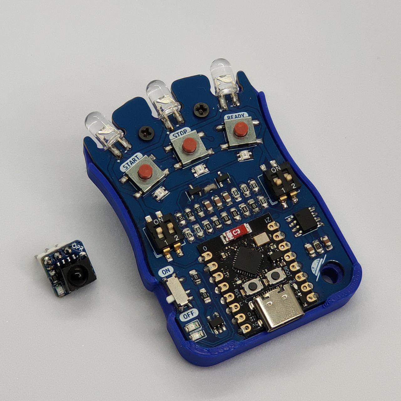
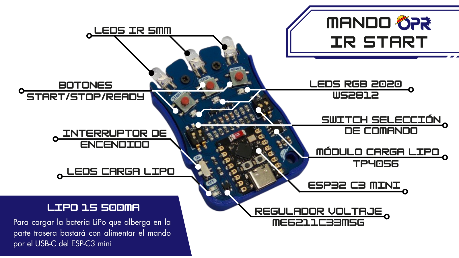
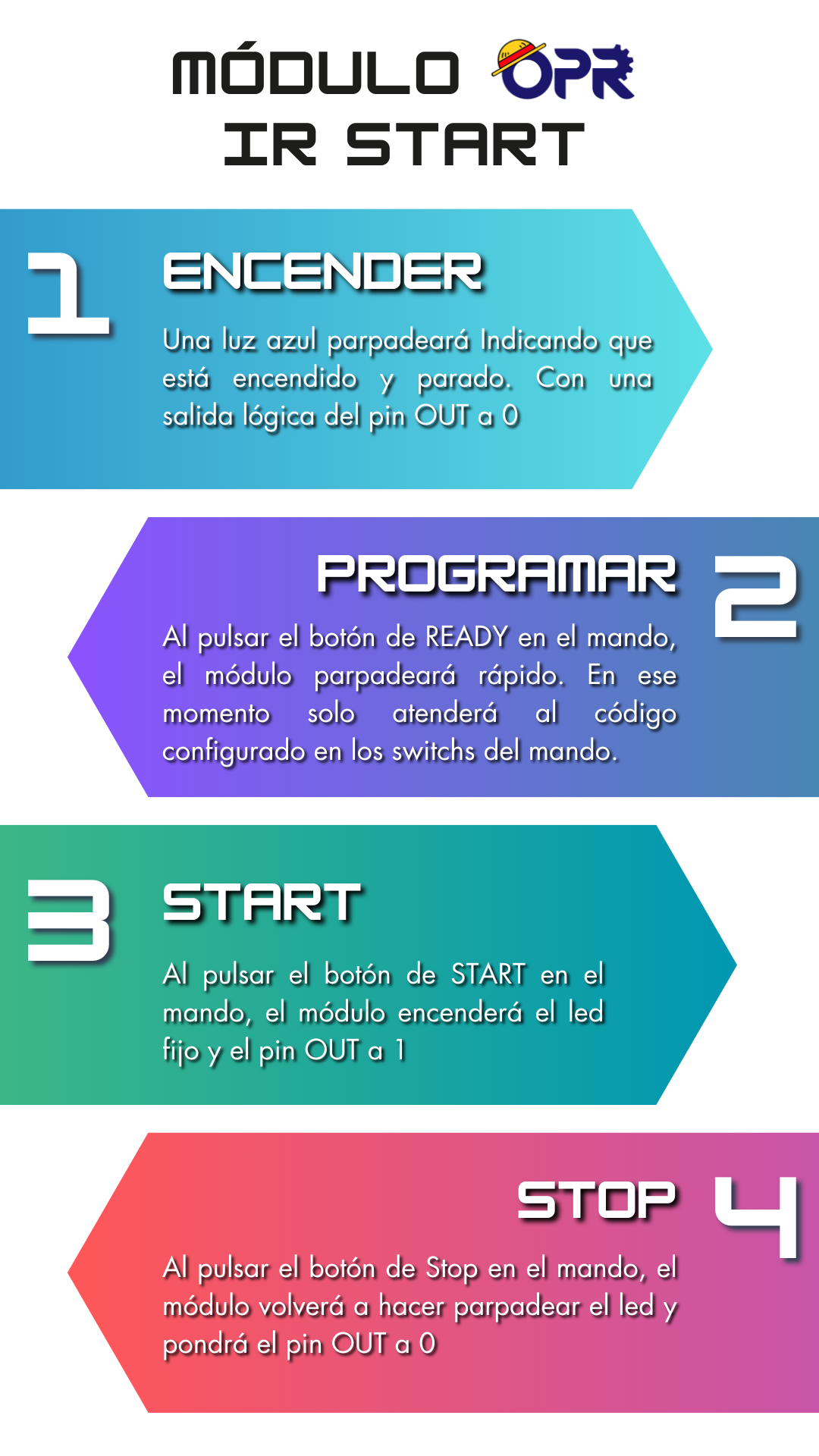
| Componente | Tecnología |
|---|---|
| Mando MCU | ESP32-C3 (RISC-V 160 MHz) |
| Módulo MCU | ATtiny13/85 (AVR 8-bit) |
| Framework | Arduino |
| Entorno | PlatformIO |
| Lenguaje | C++11 |
| Protocolos | RC5, NEC, SIRC |
| Qty | Value | Footprint | References |
|---|---|---|---|
| 1 | 0.1uF | Capacitor_SMD:C_0402_1005Metric_Pad0.74x0.62mm_HandSolder | C1 |
| 1 | 1K | Resistor_SMD:R_0805_2012Metric | R1 |
| 1 | ATtiny13A-S | custom_footprints:SOP8 | U1 |
| 1 | Conn_01x03_Socket | Connector_PinSocket_2.54mm:PinSocket_1x03_P2.54mm_Vertical | SUPPLY/OUTPUT1 |
| 1 | Conn_01x06_Socket | custom_footprints:Program_pads | PROGRAM1 |
| 1 | G*** | kibuzzard-664B97EA | kibuzzard-664B97EA |
| 1 | G*** | kibuzzard-664B9D8E | kibuzzard-664B9D8E |
| 1 | LED | LED_SMD:LED_0805_2012Metric | D1 |
| 1 | LOGO | LOGO | G*** |
| 1 | TSOP4838 | OptoDevice:Vishay_MOLD-3Pin | U2 |
OPRobots/IRStart
Módulo y mando de arranque por IR (RC-05) de robots usando Attiny13 y ESP32


Manawyrm/CMM2-JLC
Colour Maximite 2 - unofficial PCB design for automated assembly


PostTenebrasLab/PTL-IR_remote
IR remote based on esp8266 with OTA, MQTT, web server, DHT22, brightness, IRM

cue-bus/Sharp-MCP-72BGA
Breakout adapter for Sharp MCP chips in BGA72 package

LastZactionHero/defcon-silent-disco
RP2040-based DEF CON silent disco badge — KiCad project + tooling
It measures 10 × 10 mm and has 2 copper layers, 1 mm thick.
10 parts, built around the ATTINY13A-SU and TSOP4838. The full list of its parts is on this page, with links to each part's symbol and footprint where PCBKit's library has them.
From the OPRobots/IRStart repository on GitHub, at the commit this page was made from: the board is pcb_files/Module/kicad_project/IRStart - Module.kicad_pcb and its schematic pcb_files/Module/kicad_project/IRStart - Module.kicad_sch. PCBKit opens the board in the browser, with nothing to install.
Its repository publishes it under the GPL-3.0 licence: you may reuse it on that licence's terms (keep the author's notice, and for a copyleft licence share your changes alike).