2 layers123 × 87.5 mm
FastLOGIC
Neumi/fastLOGIC
An affordable Arduino-based board designed for straightforward (industrial) logic control, ideal for building small-scale automation and control solutions.
180 parts23MIT

 Manawyrm/CMM2-JLC10
Colour Maximite 2 - unofficial PCB design for automated assembly
CMM2-JLC is an open-source printed circuit board by Manawyrm, from the Manawyrm/CMM2-JLC repository on GitHub, published under the GPL-3.0 licence. It is a 4-layer board of 130 × 102 mm with 111 parts on 204 nets, routed with 4,025 tracks and 1,000 vias.
It is built around the CP2102N-A01-GQFN28R, DS18B20 and AMS1117-3.3, with the MT48LC16M16A2P-6A:G, SRV05-4 and TSOP4838 among its other parts. Its parts include 52 resistors, 37 capacitors, 9 connectors, 7 ICs and 2 diodes. It belongs with the STM32 boards of this library.


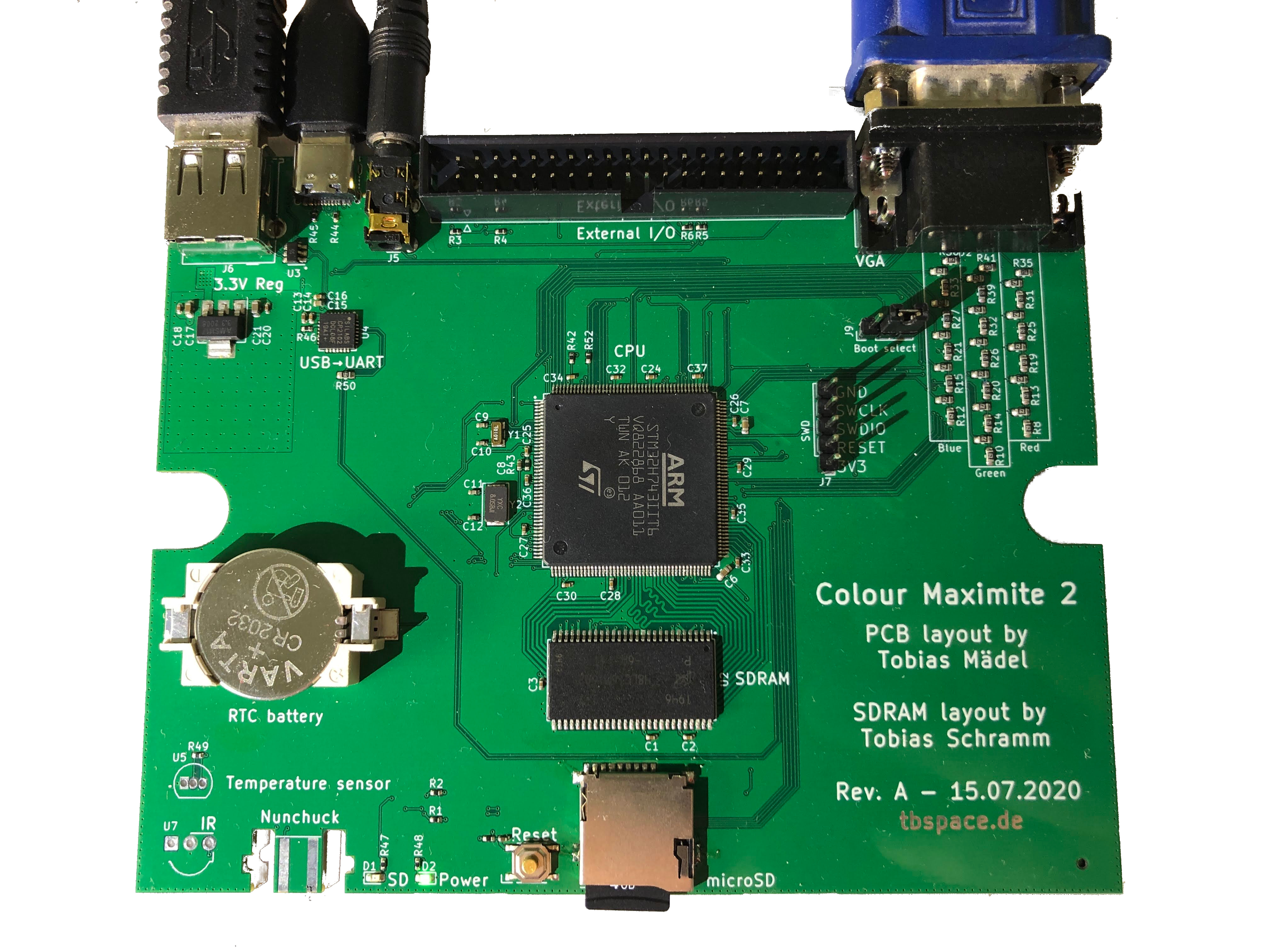
This is a open-source hardware clone PCB of the Colour Maximite 2 computer.
It's fully compatible to the original firmware and software.
| Description | Part No. | Links |
|---|---|---|
| 3.5mm audio jack | XKB PJ-3270 | LCSC |
| microSD socket | HOAUC HYC77-TF09-200 | LCSC |
| USB-C connector | Jing C167321 | LCSC |
| USB-A connector | Jing C42650 | LCSC |
| 40pin IDC | BOOMELE C9138 | LCSC |
| VGA connector | CONNFLY DS1038-15FBNSiA74-0CC | LCSC |
| Author | Components |
|---|---|
| Tobias Schramm | CR2032 Holder, 3.5mm Audiojack, MicroSD socket, reset button |
| Jan Henrik Hemsing | Nunchuck connector |
| Qty | Value | Footprint | References |
|---|---|---|---|
| 25 | 100n | Capacitor_SMD:C_0402_1005Metric | C1, C2, C3, C14, C16, C18, C20, C22, C23, C24, C25, C26, C27, C28, C29, C30 +9 |
| 19 | 240R | Resistor_SMD:R_0603_1608Metric | R10, R11, R12, R16, R17, R18, R22, R23, R24, R28, R29, R30, R34, R36, R37, R40 +3 |
| 14 | 120R | Resistor_SMD:R_0603_1608Metric | R13, R14, R15, R19, R20, R21, R25, R26, R27, R31, R32, R33, R39, R50 |
| 8 | 10k | Resistor_SMD:R_0402_1005Metric | R1, R2, R3, R4, R5, R6, R42, R52 |
| 3 | 1u | Capacitor_SMD:C_0402_1005Metric | C8, C13, C19 |
| 3 | 4.7k | Resistor_SMD:R_0402_1005Metric | R46, R48, R49 |
| 3 | 75R | Resistor_SMD:R_0603_1608Metric | R35, R38, R41 |
| 2 | 2.2u | Capacitor_SMD:C_0603_1608Metric | C6, C7 |
| 2 | 20p | Capacitor_SMD:C_0402_1005Metric | C11, C12 |
| 2 | 5.1k | Resistor_SMD:R_0402_1005Metric | R44, R45 |
| 2 | 6p | Capacitor_SMD:C_0402_1005Metric | C9, C10 |
| 1 | 100k | Resistor_SMD:R_0402_1005Metric | R51 |
| 1 | 10R | Resistor_SMD:R_0402_1005Metric | R43 |
| 1 | 10u | Capacitor_SMD:C_0603_1608Metric | C17 |
| 1 | 22u | Capacitor_SMD:C_0603_1608Metric | C21 |
| 1 | 3.3k | Resistor_SMD:R_0402_1005Metric | R47 |
| 1 | 32.768 kHz | Crystal:Crystal_SMD_3215-2Pin_3.2x1.5mm | Y1 |
| 1 | 4.7u | Capacitor_SMD:C_0402_1005Metric | C15 |
| 1 | 8 MHz | Crystal:Crystal_SMD_5032-2Pin_5.0x3.2mm | Y2 |
| 1 | AMS1117-3.3 | Package_TO_SOT_SMD:SOT-223-3_TabPin2 | U6 |
| 1 | Audio | CMM2-JLC:PJ-3270 | J5 |
| 1 | Boot select | Connector_PinHeader_2.54mm:PinHeader_1x03_P2.54mm_Vertical | J9 |
| 1 | CP2102N-A01-GQFN28 | Package_DFN_QFN:QFN-28-1EP_5x5mm_P0.5mm_EP3.35x3.35mm | U4 |
| 1 | CR2032 | CMM2-JLC:BatteryHolder_CR2032-BS-6-1 | BT1 |
| 1 | DS18B20 | Package_TO_SOT_THT:TO-92_Inline | U5 |
| 1 | EXTERNAL I/O | Connector_IDC:IDC-Header_2x20_P2.54mm_Vertical | J3 |
| 1 | MT48LC16M16A2P | Package_SO:TSOP-II-54_22.2x10.16mm_P0.8mm | U2 |
| 1 | Micro_SD_Card_Det | CMM2-JLC:HOAUC_HYC77-TF09-200 | J8 |
| 1 | Nunchuk | CMM2-JLC:nunchuck | J1 |
| 1 | POWER / GREEN | LED_SMD:LED_0603_1608Metric | D2 |
| 1 | Reset | CMM2-JLC:TS-1187A-X-X-X | SW1 |
| 1 | SD CARD / RED | LED_SMD:LED_0603_1608Metric | D1 |
| 1 | SRV05-4 | Package_TO_SOT_SMD:SOT-23-6 | U3 |
| 1 | STM32H743IITx | Package_QFP:LQFP-176_24x24mm_P0.5mm | U1 |
| 1 | SWD | Connector_PinHeader_2.54mm:PinHeader_1x05_P2.54mm_Vertical | J7 |
| 1 | TSOP4838 | OptoDevice:Vishay_MOLD-3Pin | U7 |
| 1 | USB A Host | Connector_USB:USB_A_Molex_67643_Horizontal | J6 |
| 1 | USB_C_Receptacle_USB2.0 | Connector_USB:USB_C_Receptacle_Palconn_UTC16-G | J4 |
| 1 | VGA | CMM2-JLC:DSUB-15-HD_Female_Horizontal_P2.29x2,54mm_EdgePinOffset8.63mm_Housed_MountingHolesOffset11.17mm | J2 |
Neumi/fastLOGIC
An affordable Arduino-based board designed for straightforward (industrial) logic control, ideal for building small-scale automation and control solutions.

tmilkovic51/esp32c3_devboard
A development board integrating the socket for easily swapping the ESP32-C3-WROOM-02 modules, designed in KiCad

rohamid/chroma-pixel-zeta
The minimal configuration of Chroma Pixel board for GUI application

rohamid/lcd-east-rising-backpack
PCB controller backpack for east rising LCD modules

zapta/ble_stepper_motor_analyzer
A low cost stepper motor analyzer that uses wireless BLE link to display the data in real time on a Windows/Mac/Linux PC.

TDA-2030/E-ink-screen
An assistant to help you view text and picture calendars


maddevsio/mad-navigator
Mad navigator is simple compass-like device shows direction to predefined geo point. This repository contains firmware source code and schematics for device.
It measures 130 × 102 mm and has 4 copper layers, 1.6 mm thick.
111 parts, built around the CP2102N-A01-GQFN28R, DS18B20, AMS1117-3.3 and MT48LC16M16A2P-6A:G. The full list of its parts is on this page, with links to each part's symbol and footprint where PCBKit's library has them.
From the Manawyrm/CMM2-JLC repository on GitHub, at the commit this page was made from: the board is CMM2-JLC.kicad_pcb. PCBKit opens the board in the browser, with nothing to install.
Its repository publishes it under the GPL-3.0 licence: you may reuse it on that licence's terms (keep the author's notice, and for a copyleft licence share your changes alike).