4 layers95.2 × 85.7 mm
ESP32PLC
duyhohoang/duyhohoang.github.io
Hoàng Duy — PCB Design, Embedded Systems and IoT portfolio
190 parts
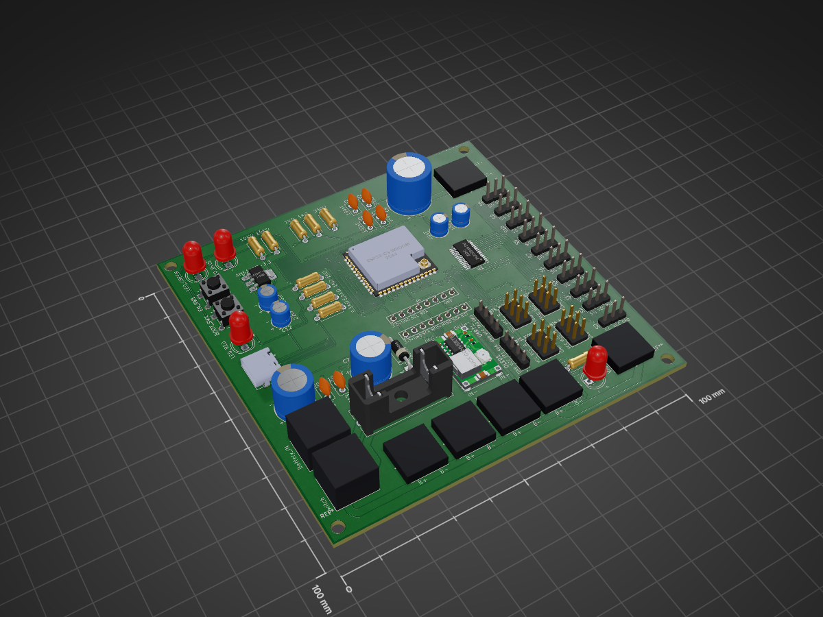
 NeuroCircuits/ESP32-S3-Rover-Controller-PCB
Custom ESP32-S3 based controller PCB for a 6-wheel robotic platform, featuring servo control, DC motor drivers, IMU, RFID, USB programming, and dedicated power regulation.
Rover drive PCB is an open-source printed circuit board by NeuroCircuits, from the NeuroCircuits/ESP32-S3-Rover-Controller-PCB repository on GitHub. It is a 2-layer board of 100 × 100 mm with 66 parts on 73 nets, routed with 950 tracks and 55 vias.
It is built around the ESP32-S3-WROOM-1U-N8R8, PCA9685PW and AMS1117-3.3, with the TYPE-C-31-M-12 among its other parts. Its parts include 13 capacitors, 10 resistors, 10 switches, 5 diodes and 5 connectors. It belongs with the robots and motor control boards and the ESP32 boards of this library.


Custom ESP32-S3 based controller PCB for a 6-wheel robotic platform, featuring servo control, DC motor drivers, IMU, RFID, USB programming, and dedicated power regulation.
This project is a custom controller PCB designed for a mobile robotic platform.
The board is built around the ESP32-S3-WROOM-1U and integrates the main electronics required for controlling the robot, reducing the need for separate wiring and controller boards.
The PCB was designed from schematic to final PCB layout in KiCad, including routing, power distribution, grounding, mounting holes, design-rule checking, and Gerber generation.
ESP32-S3-WROOM-1U main controller
USB Type-C programming interface
USB-to-UART interface
Automatic programming / reset circuitry
PCA9685 16-channel PWM controller
Support for multiple high-torque servos
Interfaces for 4 × BTS motor-driver modules
Control for 6 DC motors
MPU6050 IMU interface
RC522 RFID interface
3.3 V regulated supply for logic
5 V regulated supply
Dedicated 6 V servo power rail
High-current power input
Main power switching
Fuse protection
Multiple bulk and decoupling capacitors
Through-hole mounting holes
Two-layer PCB
Custom copper power and GND planes
Designed using KiCad.
The design includes:
| Qty | Value | Footprint | References |
|---|---|---|---|
| 10 | 61300311121 | 3_pin_male_header:3_pin_male_header | S1, S2, S3, S4, S5, S6, S7, S8, S9, S10 |
| 6 | 1711026 | 2_pin_screw_terminal_5.00mm:PHOENIX_1711026 | BTS 7960 1, BTS 7960 2, BTS 7960 3, BTS 7960 4, Vin-6V, Vout-6V |
| 5 | 1k | Resistor_THT:R_Axial_DIN0207_L6.3mm_D2.5mm_P7.62mm_Horizontal | R2, R3, R4, R5, R7 |
| 4 | 6130XX21121_61300621121 | 3 pin double row male header:61300621121 | BTS_MODULE_1, BTS_MODULE_2, BTS_MODULE_3, BTS_MODULE_4 |
| 2 | 10k | Resistor_THT:R_Axial_DIN0207_L6.3mm_D2.5mm_P7.62mm_Horizontal | R8, R9 |
| 2 | 5.1k | Resistor_THT:R_Axial_DIN0207_L6.3mm_D2.5mm_P7.62mm_Horizontal | R1, R6 |
| 2 | 61300411121 | 4_pin_male_header:WURTH_61300411121 | OLED1, UART1 |
| 1 | 1000uF (for main power rail) | Capacitor_THT:CP_Radial_D10.0mm_P5.00mm | C3 |
| 1 | 100nF ( for power rail) | Capacitor_THT:C_Disc_D5.0mm_W2.5mm_P2.50mm | C4 |
| 1 | 100nF (3.3v buck) | Capacitor_THT:C_Disc_D5.0mm_W2.5mm_P2.50mm | C13 |
| 1 | 100nF (5v buck) | Capacitor_THT:C_Disc_D5.0mm_W2.5mm_P2.50mm | C8 |
| 1 | 100nF (6v buck) | Capacitor_THT:C_Disc_D5.0mm_W2.5mm_P2.50mm | C11 |
| 1 | 100nF (esp) | Capacitor_THT:C_Disc_D5.0mm_W2.5mm_P2.50mm | C6 |
| 1 | 100nF (servo driver) | Capacitor_THT:C_Disc_D5.0mm_W2.5mm_P2.50mm | C2 |
| 1 | 10uF (5v regulator) | Capacitor_THT:CP_Radial_D5.0mm_P2.00mm | C10 |
| 1 | 10uF (Servo driver) | Capacitor_THT:CP_Radial_D5.0mm_P2.00mm | C1 |
| 1 | 10uF (with esp32) | Capacitor_THT:CP_Radial_D5.0mm_P2.00mm | C5 |
| 1 | 1N5819 | Diode_THT:D_DO-41_SOD81_P10.16mm_Horizontal | D4 |
| 1 | 2 pin screw terminal | 2_pin_screw_terminal_5.00mm:PHOENIX_1711026 | J1 |
| 1 | 2 pin screw terminal for button | 2_pin_screw_terminal_5.00mm:PHOENIX_1711026 | J3 |
| 1 | 2200uF (6v buck) | Capacitor_THT:CP_Radial_D12.5mm_P5.00mm | C9 |
| 1 | 22uF (3.3v regulator) | Capacitor_THT:CP_Radial_D5.0mm_P2.00mm | C12 |
| 1 | 330 | Resistor_THT:R_Axial_DIN0207_L6.3mm_D2.5mm_P7.62mm_Horizontal | R10 |
| 1 | 470uF (5v buck) | Capacitor_THT:CP_Radial_D10.0mm_P5.00mm | C7 |
| 1 | AMS1117-3.3 | Package_TO_SOT_SMD:SOT-223-3_TabPin2 | U4 |
| 1 | ESP32-S3-WROOM-1U-N8R8 | ESP32-S3-WROOM-1U-N8R81:XCVR_ESP32-S3-WROOM-1U-N8R8 | U2 |
| 1 | Fuse | fuse_holder:FUSE_4628 | F1 |
| 1 | MPU6050 | 8 pin header male:61300811121 | J4 |
| 1 | PCA9685PW | Package_SO:TSSOP-28_4.4x9.7mm_P0.65mm | U1 |
| 1 | RC522 | 8 pin header male:61300811121 | J5 |
| 1 | S1 | Push_button_4_pin:4_pin_tacticle_push_button | EN_SW1 |
| 1 | S2 | Push_button_4_pin:4_pin_tacticle_push_button | BOOT_SW1 |
| 1 | TYPE-C-31-M-12 | TYPE-C-31-M-12:HRO_TYPE-C-31-M-12 | J2 |
| 1 | buck 3.3v led | LED_THT:LED_D5.0mm | D2 |
| 1 | buck converter 5v | Mini DC buck:Mini360_step-down (3) | U3 |
| 1 | power_led | LED_THT:LED_D5.0mm | D1 |
| 1 | servo_led | LED_THT:LED_D5.0mm | D5 |
| 1 | status_led | LED_THT:LED_D5.0mm | D6 |
The 62 most common of 66 parts.
duyhohoang/duyhohoang.github.io
Hoàng Duy — PCB Design, Embedded Systems and IoT portfolio


leeyumsk/IRL-Subtitles
Using techniques similar to human perception to localize sounds and speakers.


felixfelix-bot/balloon-fresh
Open-source pico-balloon hardware and firmware, multi-radio LoRa/FLRC mesh networking, ground stations, and RF range-test tooling.

lewipewi/esp-32-gaming-console
A custom PCB handheld built to run Game Boy games, inspired by the original DMG. Designed from scratch in KiCad — schematic, layout, BOM and firmware.

lewipewi/esp-32-gaming-console-v2
A handheld Game Boy (DMG) emulator console built around an ESP32-S3, designed from scratch in KiCad. The target game is Pokémon Red/Blue.

It measures 100 × 100 mm and has 2 copper layers, 1.6 mm thick.
66 parts, built around the ESP32-S3-WROOM-1U-N8R8, PCA9685PW, AMS1117-3.3 and TYPE-C-31-M-12. The full list of its parts is on this page, with links to each part's symbol and footprint where PCBKit's library has them.
From the NeuroCircuits/ESP32-S3-Rover-Controller-PCB repository on GitHub, at the commit this page was made from: the board is KiCad/PCB/Rover-drive-PCB.kicad_pcb and its schematic KiCad/Schematic/Rover-drive.kicad_sch. PCBKit opens the board in the browser, with nothing to install.
Its repository states no licence, so its author keeps all rights: ask NeuroCircuits before reusing the design.