
2 layers44.5 × 46.9 mm
OSO SWAT B1-jig
joeycastillo/Sensor-Watch
A board replacement for the classic Casio F-91W wristwatch
31 parts2.1k

An Ultra Low Cost PIC programmer with Arduino Uno/Nano (hardware + software)
PicArd is an open-source printed circuit board by NelsonBittencourt, from the NelsonBittencourt/PicArd repository on GitHub, published under the MIT licence. It is a 2-layer board with 31 parts on 44 nets, routed with 147 tracks and 0 vias.
Its parts include 14 resistors, 7 transistors, 4 capacitors, 3 diodes and 1 connector. It belongs with the interfaces and adapters boards and the AVR (ATmega, ATtiny) and PIC boards of this library.
As my projects became increasingly complex (and required more discrete components), I decided to migrate several of them from "discrete" electronics to microcontrollers.
During this transition, I evaluated various microcontroller families available and I selected PICs because they are easy to find, cost-effective and meet my requirements.
To keep my projects as low-cost as possible (and also as a personal challenge), I made two decisions: a) to purchase some PIC12F675s (the cheapest here in Brazil) and some PIC16F819s and b) to build my own PIC programmer!
Thus, the PicArd (PIC + Arduino) Project was born!
PicArd IS:
PicArd ISN'T:
As reported by wocard2, the voltage on ICSP pins of current hardware is 5 V. This voltage is not suitable for PICs whose maximum operating voltage is below 5 V
$\color{red}{\textbf{Carefully check the operating voltage of your PIC to avoid potential damage!}}$
A new hardware revison with level shifters is under development and will resolve the mismatch between 5 V and lower voltages.
The PicArd Hardware consists of:
Don't be intimidated by this list! It looks very complex (except for the Arduino, perhaps), but to assemble everything, I only used seven bipolar junction transistors (BC547s and BC557s) and few passive components. Check out the breadboard:
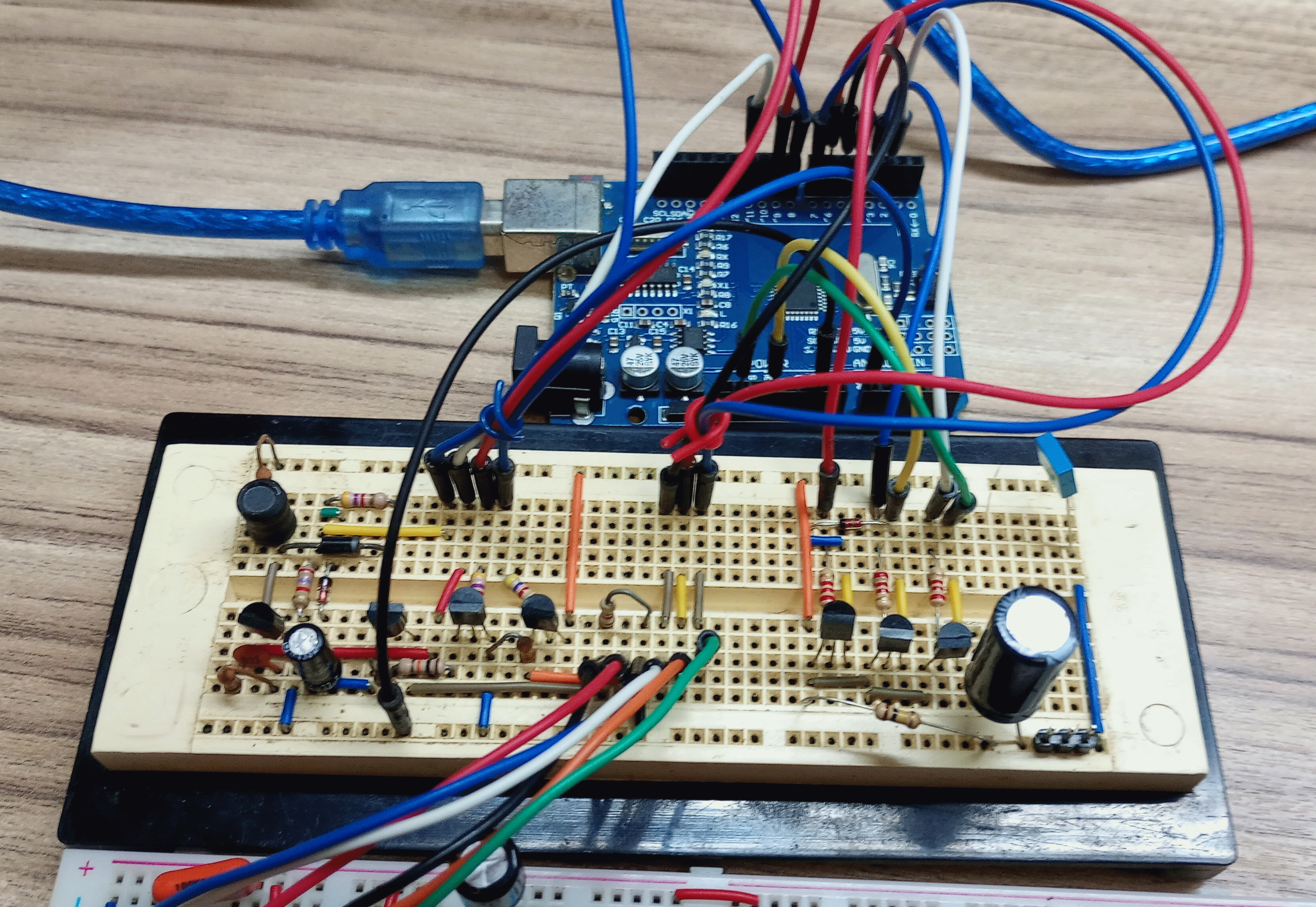 Figure 1a. PicArd Breadboard |
If you prefer, you can assemble the PicArd Programmer as a shield. Figure 1b shows a rendered image of the Arduino Uno Shield that I created.
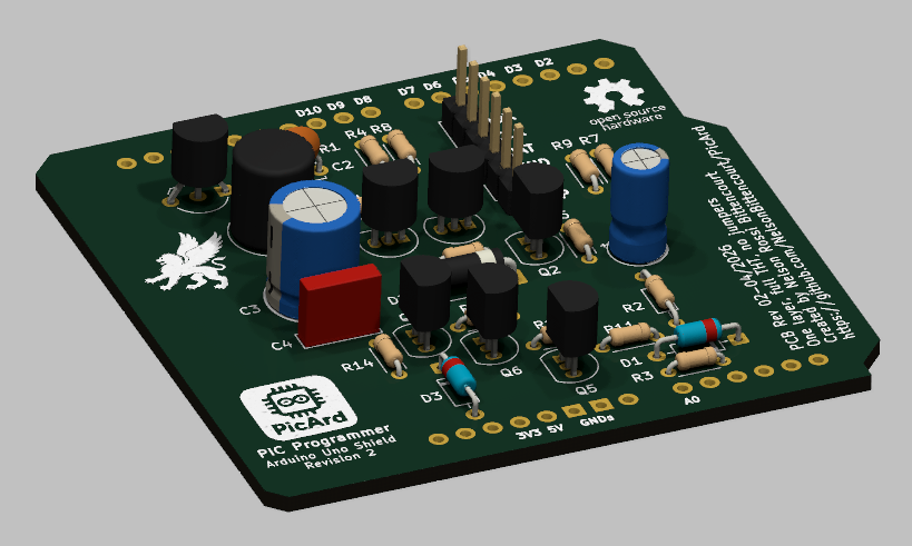 Figure 1b. PicArd Arduino Uno Shield |
Important: For new projects, always use PicArd Programmer Hardware Revision 2 and the latest software versions (>= 0.45).
Gerber files for the fabrication of this shield are available in Uno Shield folder.
The following figure shows Arduino Uno R3 connections to PicArd:
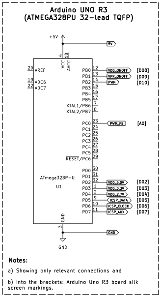 Figure 2. Arduino UNO R3 Connections |
My Arduino R3 clone board has a ATMEGA328PU in a TQFP package. The pin numbers above refer to this package. If your Arduino has another package, consider making connections using identifications into the brackets (PCB silk screen) or the full pin name (e.g. PORT0).
The connections between Arduino R3 and PicArd are:
Table 1. Labels Descriptions
| Label | Description |
|---|---|
| 5V | Positive 5 V (remember, Arduino needs to be connected to PC USB) |
| 3V3 | Positive 3.3 V (from Arduino Uno) |
| PWM | PWM signal for DC/DC boost converter |
| PWM_FB | PWM voltage feedback |
| VDD_ONOFF | Turns on/off VDD to device |
| VPP_ONOFF | Turns on/off VPP to device |
| VDD_5.0V | Select/Unselect 5.0 V as VDD |
| VDD_3.3V | Select/Unselect 3.3 V as VDD |
| VDD_2.7V | Select/Unselect 2.7 V as VDD |
| ICSP_DATA | In-circuit serial programming (ICSP) data pin |
| ICSP_CLOCK | ICSP clock pin |
| ICSP_AUX | ICSP for Low Voltage Programming (LVP) |
| VDD | Selected VDD |
| VDD_DEVICE | Device VDD Pin |
| VPP | Programming voltage |
| VPP_DEVICE | Device VPP Pin |
| GND | Ground |
DC-DC boost converter is responsible for raising voltage from 5 V to programming voltage (VPP) required by PICs. This module is optional if you intend to use only PICs that support LVP.
I designed this circuit to operate with VPPs between 2 V and 13 V.
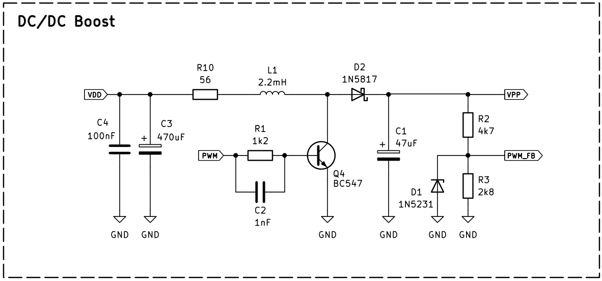 Figure 3. DC/DC booster |
PWM signal from Arduino controls Q4 through R1 and C2 (capacitor added to improve switching speed). L1, D2 and C1 completes basic DC/DC boost circuitry. A voltage divider (R2 and R3) is used apply a secure voltage (<=5.0V) to PWM_FB pin. As an additional precaution, I added D1 (5.1V zener diode).
The PICs' supply voltages (VDD) can range from 2.7 V to 5.0 V. Since the Arduino Uno has voltage regulators for 3.3 V and 5.0 V, I used the circuit below to allow the selection of the correct voltage. By controlling pins D02 (VDD_5.0V), D03 (VDD_3.3V), and D04 (VDD_2.7V), we can obtain 5.0 V, 3.3 V, and approximately 2.7V, which covers almost all devices.
This approach eliminates the necessity of a Low Dropout Regulator (LDO), reducing the project cost.
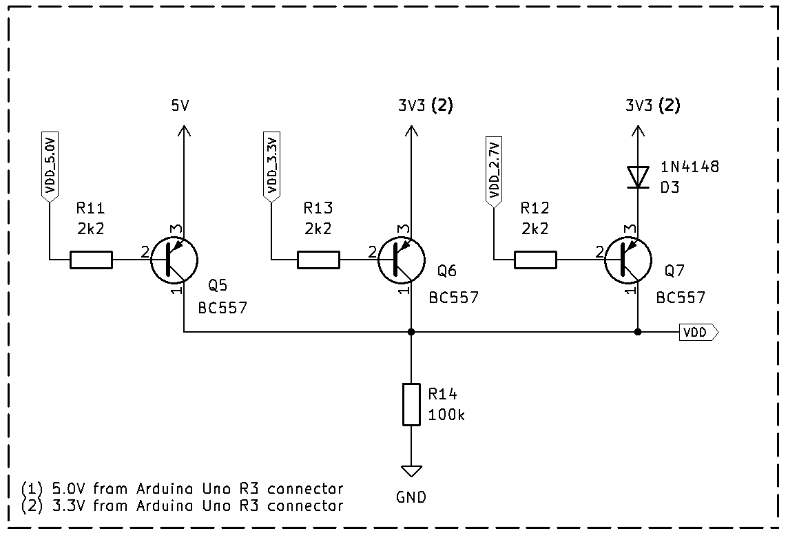 Figure 4. VDD Selection Control |
VPP (from DC/DC converter) and VDD (from above circuit) must be applied to PIC at specific times. Therefore, Arduino needs to send VPP_ONOFF and VDD_ONOFF signals to control when PIC will receive this voltages.
The circuit below shows my solution:
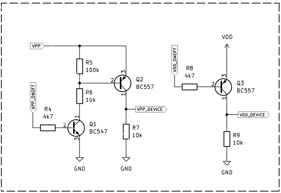 Figure 5. Voltages Control |
VPP_DEVICE and VDD_DEVICE must be applied to PIC's correspondent pins.
Connecting PicArd to PIC microcontrollers is pretty simple, just follow Microchip's programming specifications.
The figures below show two connection examples:
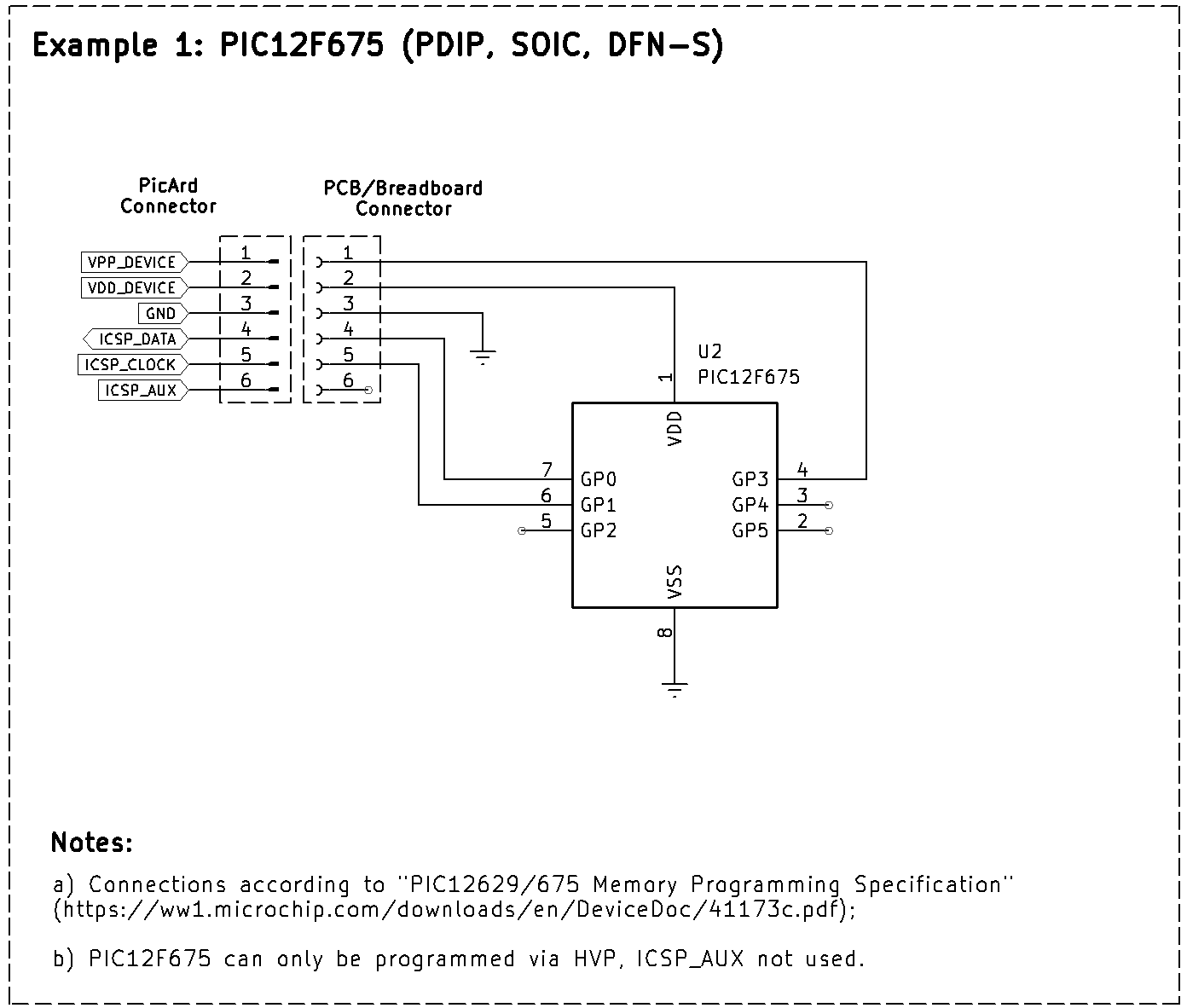 Figure 6. PicArd connected to PIC12F675 |
Each PIC microcontroller family has its own programming specifications. For PIC12F675 in the example above, see: PIC12F629/675 Memory Programming Specification
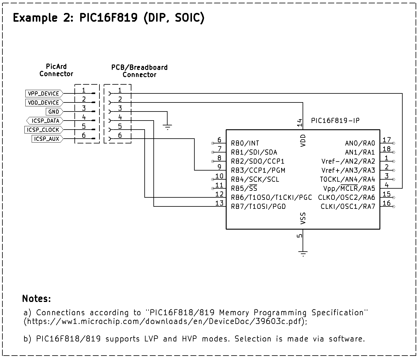 Figure 7. PicArd connected to PIC16F819 |
This example follows PIC16F818/819 Memory Programming Specification.
The link below contains all the schematic diagrams we have seen so far (I also included a page with typical voltage and signal values):
PicArd requires two sets of code:
Arduino software must be uploaded to Arduino Uno R3. Download it from Release section
PicArd PC software has two flavors: GUI or console. Both have been compiled for Windows and Linux, and their functions are:
As of version 0.45, PC applications also handle Calibration Words. Because I had previously created two additional record types to the Intel HEX standard (06 for BandGaps and 07 for OSCCALs), I decided to call the input file format as Picard Hex Files (.pchx).
For further details and examples regarding this format, refer to pchx format.
Warning 1: Database file (pic_devices.dat) must be in the same folder that PicArd executable.
Warning 2: From version 0.45 onwards, the picard.ini file must be provided. See further details about this file in C.2.1 or C.2.2.
Warning 3: In Linux, ensure that your user has read and write access to USB devices.
Download PicArd's PC software in Releases section.
GUI version consists of a single main window, as shown in Figure 8.It is self-explanatory.
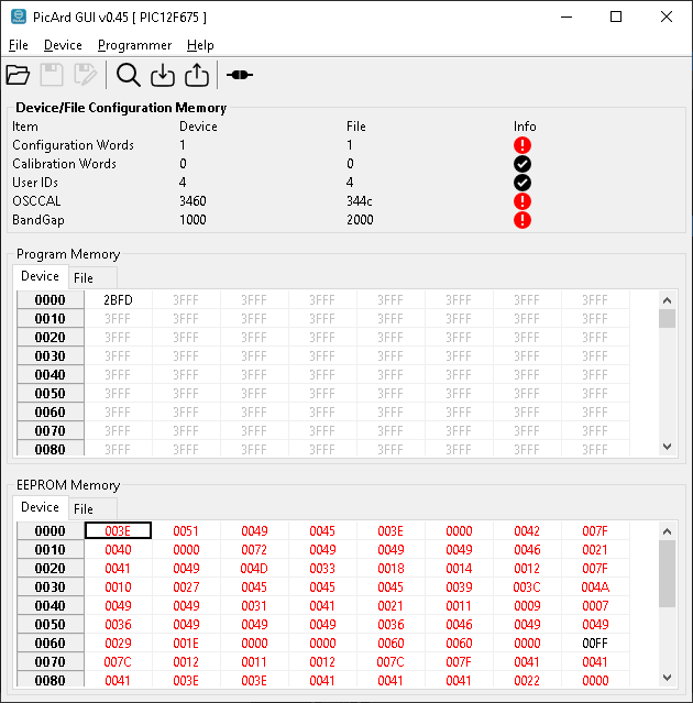 Figure 8. PicArd GUI Main Window |
This version generates two log files (in the executable directory):
First one is osccals_bandgaps.txt, which will save the OSCCALs, BandGaps and Calibration Words values every time a device is read. This information is useful to avoid losing factory calibration data for certain PICs.
The second file, picard.log, logs the steps executed by the application to help identify potential errors.
Some features have not yet been implemented, such as "Save PCHx file".
PicArd GUI files are named picard_gui_<version_number>_windows.zip and picard_gui_<version_number>_linux.zip.
From version 0.45 onwards, the picard.ini file must be provided. Although this file is included in every package in the release folder, it must be modified by the user before launching the application.
The picard.ini sintax is:
last_usb:none
last_device:none
voltage_divider_top_resistor:0
voltage_divider_bottom_resistor:0
programming_voltage_stability_check:0
last_usb and last_device (GUI only) can be left as "none".
voltage_divider_top_resistor and voltage_divider_bottom_resistor represent the values of resistors R2 and R3 in the boost converter feedback voltage divider (Figure 3). Measure the actual values of your circuit and enter them as integers in this file.
For example, my prototype had R2 = 4074.9 ohms and R3 = 2675.1 ohms. The picard.ini is:
last_usb:none
last_device:none
voltage_divider_top_resistor:4705
voltage_divider_bottom_resistor:2675
programming_voltage_stability_check:0
When programming_voltage_stability_check is enabled (value 1), the Picard Hardware waits for the boost converter's output voltage to stabilize. This feature worked well in my experiments, but some people did not achieve good results (see Issue #1 ,Portuguese only).
Starting with version 0.45, I decided to simplify the commands for PicArd console version.
If, for some reason, you continue using the old versions, simply type picard.exe or ./picard to see the syntax.
The picard.ini file must also be used for the console version. Here a example for this file in console application directory:
voltage_divider_top_resistor:4705
voltage_divider_bottom_resistor:2675
programming_voltage_stability_check:0
Replace the values above with your measured values.
picard -c <serial port> -d <device name> [-r output_file] [-w hex_file]where:
Example 1: Verify if PIC12F675 exist in database (pic_device.dat):
picard -d PIC12F675

PicArd 0.45 - PIC Programmer using Arduino UNO
Nelson Rossi Bittencourt - https://github.com/nelsonbittencourt/picard

Device found
Device name : PIC12F675
Device ID   : 4032 (fc0)
Family name : Midrange/Standard
LVP support : No
Nothing to do!
Example 2: Read a PIC12F675 (Arduino on COM3) to file pic_output.pchx
picard -c COM3 -d PIC12F675 -r pic_output.pchx

PicArd 0.45 - PIC Programmer using Arduino UNO
Nelson Rossi Bittencourt - https://github.com/nelsonbittencourt/picard

Device found
Name        : PIC12F675
ID          : 4032 (fc0)
Family      : Midrange/Standard
LVP support : No

Programmer booted.
VDD setted to: 5V
Programming entry mode: HVP
Setting VPP to : 12V

Reading device configuration:
Reading Device ID: Ok [fc0]
Reading User IDs: Ok
To avoid errors or calibration lost, PicArd will save OSCCAL, BandGap and Calibration Word(s) into osccals_bandgaps.txt.
Feel free to write down values to reduce data loss probability.
Reading OSCCAL : Ok [3460]
Reading Configuration Word(s): Ok
Reading Program Memory: OkFor PIC read operations, the console version of PicArd will save the read data in .pchx format.
Example 3: Send hex data (program.hex) from PC to PIC12F675:
picard -c COM3 -d PIC12F675 -w program.hexWill send all necessary data (program data, EEPROM data, configuration words, etc) to device.
PicArd Console files are named picard_console_<version_number>_windows.zip and picard_console_<version_number>_linux.zip.
PicArd is based on the same scripts and code used in the PicKit2. These scripts, as well as the device information, are stored in the pic_devices.dat file. I have utilized the file bravely maintained and updated by Jaka and Anobium.
If you want to support Anobium's efforts in device file, consider buying PICkitPlus software.
My goal was to implement all the script codes contained in the "PICkit 2 Interface Guide" to allow the programming of largest number of devices possible. Studying the scripts and datasheets, I decided to leave out PIC32, KEELOQ, and EEPROM models. Furthermore, I was unable to read all the datasheets and could not test all devices.
If your device utilizes a script whose code is implemented in PicArd, there is a good chance that it can be read/programmed by the application. However, this is not guaranteed...
Below are the codes that I have already implemented and those that still need to be implemented:
Table 2. Implemented script codes
| Code | Function/Mnemonic | Arduino Uno Label / Comments |
|---|---|---|
| 0xFF | VDD ON | VDD_ONOFF / Turns on PNP transistor (Q3); Device VDD = VDD |
| 0xFE | VDD OFF | VDD_ONOFF / Turns off PNP transistor (Q3); Device VDD = 0V |
| 0xFD | VDD GND ON | VDD_ONOFF / Implemented as 0xFE |
| 0xFC | VDD GND OFF | VDD_ONFF / Implemented as 0xFF |
| 0xFB | VPP ON | VPP_ONOFF / Turns on NPN/PNP pair (Q1 and Q2); Device VPP = VPP |
| 0xFA | VPP OFF | VPP_ONOFF / Turns off NPN/PNP pair (Q1 and Q2); Device VPP = VPP |
| 0xF9 | VPP PWM ON | Mapped only. Not necessary (PWM always on in HVP mode) |
| 0xF8 | VPP PWM OFF | Mapped only. Not necessary (PWM always on in HVP mode) |
| 0xF7 | MCLR GND ON | Mapped only. (VPP pull-down resistor) |
| 0xF6 | MCLR GND OFF | Mapped only. (VPP pull-down resistor) |
| 0xF5 | Busy led on | Arduino built-in LED turns on |
| 0xF4 | Busy led off | Arduino built-in LED turns off |
| 0xF3 | Set ICSP Pins | ICSP_DATA (D05) and ICSP_CLOCK (D06) |
| 0xF2 | Write byte literal | - |
| 0xF1 | Write byte buffer | - |
| 0xF0 | Read byte buffer | - |
| 0xEF | Read byte | - |
| 0xEE | Write bits literal | - |
| 0xED | Write bits buffer | - |
| 0xEC | Read bits buffer | - |
| 0xEB | Read bits | - |
| 0xE9 | Loop | - |
| 0xE8 | Delay long | - |
| 0xE7 | Delay short | - |
| 0xE6 | If equal goto | Implemented, not tested |
| 0xE5 | If greater goto | Implemented, not tested |
| 0xE4 | Goto index | - |
| 0xE3 | Exit script | Mapped only. Not used |
| 0xDD | Loop buffer | - |
| 0xDB | Pop download | - |
| 0xDA | COREINST18 | - |
| 0xD9 | COREINST24 | Not tested |
| 0xD8 | NOP24 | Not tested |
| 0xD7 | VISI24 | Not tested |
| 0xD6 | RD2_BYTE_BUFFER | Implemented as 0xF0. Not tested |
| 0xD5 | RD2_BITs_BUFFER | Implemented as 0xEC. Not tested |
| 0xD4 | WRITE_BUFWORD_W | Not tested |
| 0xD3 | WRITE_BUFBYTE_W | Not tested |
| 0xD2 | WRITE_BUFBYTE_W | Not tested |
| 0xD1 | CONST_WRITE_DL | Not tested |
| 0xCF | Set Aux | ICSP_AUX (D07) |
Table 3. Not implemented script codes
| Code | Function/Mnemonic | Comments |
|---|---|---|
| 0xEA | Set ICSP speed | PC-Arduino Uno communication at constant speed (19200 bauds) |
| 0xE2 | Peek SFR | Not found in pic_devices.dat file |
| 0xE1 | Poke SFR | Not found in pic_devices.dat file |
| 0xE0 | ICDSLAVE_RX | Only for debug scripts |
| 0xDF | ICDSLAVE_TX_LIT | Only for debug scripts |
| 0xDE | ICDSLAVE_TX_BUF | Only for debug scripts |
| 0xDC | ICSP_STATES_BUFFER | Only for debug scripts |
| 0xD1 | WRITE_BITS_LIT_HLD | 33CK_ChpErasePrep only |
| 0XD0 | WRITE_BITS_BUF_HLD | HCS only |
| 0xCE | Aux State Buffer | Not found in pic_devices.dat file |
| 0xC8 to 0xCD | I2C commands | Not used in PicArd |
| 0xC3 to 0xC7 | SPI commands | Not used in PicArd |
| 0xC0 to 0xC2 | ICDSLAVE debug commands | Only for debug scripts |
| 0xB3 to 0xBC | JT2 commands | Not used in PicArd |
| 0xBF | MEASURE_PULSE | Not used in PicArd |
| 0xBE | UNIO_TX | EEPROMs only |
| 0xBD | UNIO_TX_RX | EEPROMs only |
Table 4. Tested Devices
| Device | Testers | Notes |
|---|---|---|
| PIC10F322 | @wocard2 | |
| PIC12F1572 | @wocard2 and @lalo-uy | |
| PIC12F1822 | @wocard2 | |
| PIC12F1840 | @wocard2 | |
| PIC12F508 | @wocard2 | Device without ID. Read ID skipped by software |
| PIC12F629 | @girardim | |
| PIC12F675 | @NelsonBittencourt | |
| PIC16C84 | @lalo-uy | |
| PIC16F13145 | @wocard2 | |
| PIC16F1454 | @wocard2 | |
| PIC16F18324 | @wocard2 | HVP only. Internal VPP pull-up too strong |
| PIC16F19156 | @wocard2 | |
| PIC16F1938 | @girardim | |
| PIC16F819 | @NelsonBittencourt | |
| PIC16F886 | @girardim and @lalo-uy | |
| PIC18F14K50 | @wocard2 | HVP only. Internal VPP pull-up too strong |
https://nrbenergia.azurewebsites.net/
or
http://www.nrbenergia.somee.com/
| Qty | Value | Footprint | References |
|---|---|---|---|
| 5 | 2N5401 | Package_TO_SOT_THT:TO-92_Inline_Wide | Q2, Q3, Q4, Q6, Q7 |
| 3 | 10k | Resistor_THT:R_Axial_DIN0207_L6.3mm_D2.5mm_P10.16mm_Horizontal | R10, R12, R13 |
| 3 | 2k2 | Resistor_THT:R_Axial_DIN0207_L6.3mm_D2.5mm_P10.16mm_Horizontal | R5, R6, R7 |
| 3 | 4k7 | Resistor_THT:R_Axial_DIN0207_L6.3mm_D2.5mm_P10.16mm_Horizontal | R3, R9, R14 |
| 2 | 100k | Resistor_THT:R_Axial_DIN0207_L6.3mm_D2.5mm_P10.16mm_Horizontal | R8, R11 |
| 2 | 2N5551 | Package_TO_SOT_THT:TO-92_Inline_Wide | Q1, Q5 |
| 1 | 100n | Capacitor_THT:C_Axial_L3.8mm_D2.6mm_P7.50mm_Horizontal | C2 |
| 1 | 1N4148 | Diode_THT:D_DO-35_SOD27_P7.62mm_Horizontal | D3 |
| 1 | 1N5231 | Diode_THT:D_DO-201_P15.24mm_Horizontal | D2 |
| 1 | 1N5817 | Diode_THT:D_DO-41_SOD81_P10.16mm_Horizontal | D1 |
| 1 | 1k2 | Resistor_THT:R_Axial_DIN0207_L6.3mm_D2.5mm_P10.16mm_Horizontal | R2 |
| 1 | 1n | Capacitor_THT:C_Axial_L3.8mm_D2.6mm_P7.50mm_Horizontal | C3 |
| 1 | 2k8 | Resistor_THT:R_Axial_DIN0207_L6.3mm_D2.5mm_P10.16mm_Horizontal | R4 |
| 1 | 2m2 | Inductor_THT:L_Axial_L5.0mm_D3.6mm_P10.00mm_Horizontal_Murata_BL01RN1A2A2 | L1 |
| 1 | 470u | Capacitor_THT:CP_Radial_D10.0mm_P5.00mm | C1 |
| 1 | 47u | Capacitor_THT:CP_Radial_D5.0mm_P2.50mm | C4 |
| 1 | 56 | Resistor_THT:R_Axial_DIN0207_L6.3mm_D2.5mm_P10.16mm_Horizontal | R1 |
| 1 | Arduino_Nano_v3.x | Module:Arduino_Nano | A1 |
| 1 | Conn_01x06_Pin | Connector_PinHeader_2.54mm:PinHeader_1x06_P2.54mm_Vertical | J1 |
joeycastillo/Sensor-Watch
A board replacement for the classic Casio F-91W wristwatch

hoglet67/RGBtoHDMI
Bare-metal Raspberry Pi project that provides pixel-perfect sampling of Retro Computer RGB/YUV video and conversion to HDMI

hackclub/OnBoard
💡 Join 1,000 teenagers and make your first PCB with a $100 grant!

openwch/ch32v003
CH32V003 is an ultra-cheap RISC-V MCU with 2KB SRAM, 16KB flash, and up to 18 GPIOs that sells for under $0.10

Luos-io/luos_engine
Open-source and real-time orchestrator for cyber-physical-systems, to easily design, test and deploy embedded applications and digital twins.

BlueAndi/Pixelix
Full RGB LED matrix, based on an ESP32 and WS2812B LEDs or emulated LEDs on TFT.


31 parts. The full list of its parts is on this page, with links to each part's symbol and footprint where PCBKit's library has them.
From the NelsonBittencourt/PicArd repository on GitHub, at the commit this page was made from: the board is third_party/lalo_uy/Nano_HW/Picard.kicad_pcb and its schematic third_party/lalo_uy/Nano_HW/Picard.kicad_sch. PCBKit opens the board in the browser, with nothing to install.
Its repository publishes it under the MIT licence: you may reuse it on that licence's terms (keep the author's notice, and for a copyleft licence share your changes alike).