Skip to the content
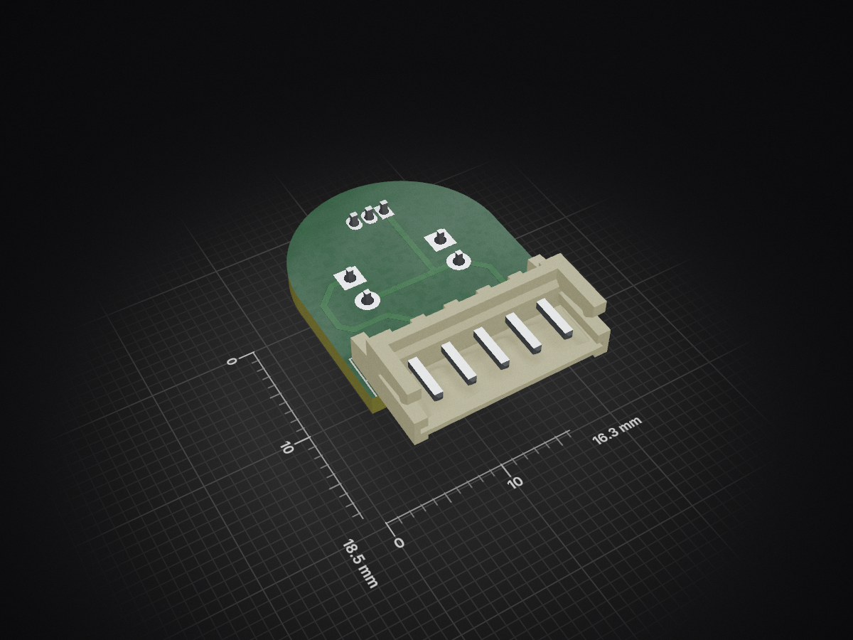
2 layers16.3 × 18.5 mmSensorPCB, the printed circuit board in 3D

A subsystem that measures the RPM of the primary and secondary on the CVT

Size
16.3 × 18.5 mm
Copper layers
2
Thickness
1.6 mm
Parts
4
Nets
5
Pads
12
Tracks, vias
30, 0
Routed
Yes
KiCad
KiCad 8.0 (file 20240108)
Created
30 Sep 2023
Updated
26 Apr 2026

Overview

SensorPCB is an open-source printed circuit board by NJIT-Highlander-Racing-Electrical, from the NJIT-Highlander-Racing-Electrical/CVT-Tachometer repository on GitHub. It is a 2-layer board of 16.3 × 18.5 mm with 4 parts on 5 nets, routed with 30 tracks and 0 vias.

Its parts include 2 diodes, 1 IC and 1 connector.

README

README.md

CVT-Tachometer

A subsystem that measures the RPM of the primary and secondary on the CVT. This subsystem also has a temperature sensor to detect if the CVT is overheating.

2024-2025 Design Goals

  • Everything last year seemed to work well, but a few improvements to the existing system could be made:
    • Software
      • Improve program to do more analog reads and spend less time processing data
        • This may involve constants that are only calculated once during setup, faster math functions, fewer delays, etc
      • Use the analog reads for IR sensors on both ADC1 and ADC2 to prevent any issues.
    • Sensor Enclosures
      • the sensor housings should be made out of something other than PLA
      • they should be able to fit custom PCBs with connectors
      • the hood around the emitter and receiver should be enlarged to prevent anything else from reflecting other than what is directly in front
    • PCBs for sensors
      • the wiring from the sensors to the main electronics housing were tough to do
      • A small PCB for the electronics would be nicer than hand soldering wires
      • A connector would also be good so that they can be removed/swapped easily
        • Maybe 1x4 or 1x5 or 1x6 JST depending on how many conductors we need going to each board
    • Additional TMP36 Sensor
      • Another TMP36 temperature sensor can be added so that there is only one version of the sensor PCB, and we get a better idea of the temperature gradient within the CVT case (primary vs secondary).
    • Additional Note
      • On the IR receiver output, have it split to two GPIO. One leg has a potentiometer (0-10k?) between the output and the GPIO for finding the optimal resistance. Also make sure it has a small series resistor to prevent resistance from dropping completely to zero. The other GPIO has a fixed resistor that can be added after the fact that will be used in the long term.

Hardware Components:

  • IR Sensors that point at primary and secondary.
  • These can detect when a white stripe on the CVT passes by (one revolution)
  • Microcontroller to convert the number of revolutions per second into an RPM value for dashboard and DAS (via CAN-Bus)
    • Uses ESP32 and TJA1051T CAN-Bus transceiver
  • TMP36 Temperature Sensor to look at ambient temperature in the CVT case
  • Sends a bit via CAN-Bus to turn on an overheating status LED on the dashboard

Notes

  • Super-Bright IR LEDs support an output current of 100mA with a forward voltage of 1.6V. This means a voltage drop of 5V-1.6V = 3.4V across the 1W resistor. To achieve a current of roughly 75mA, we are using a 47 ohm resistor

    • 5V -> IR LED -> Resistor -> Ground
  • Using standard infrared photodiodes, we can simply power the IR leds without needing a 38kHz pulse rate

    • 5V -> IR Diode -> Resistor -> Ground (sample signal between diode and resistor voltage divider)
  • Temperature sensor is TMP36

    • 5V - > TMP36 VCC, GND -> TMP 36 GND, VOUT -> GPIO
  • Connections from the LEDs/sensors to the main body should be sealed/waterproof

  • The holes in the CVT case should be 20mm

  • The infrared diode appears to act like a variable resistor, but voltage polarity must be + on cathode (short negative leg) and - on anode (short positive leg)

  • The software utilizes the dual core functionality of the ESP32

    • Core 1 reads primaryRPM and deals with CAN-Bus communication
      • It is very important that all other processing is kept to a minimum to ensure primaryRPM is accurately read
    • Core 0 solely reads secondaryRPM

Previous Issues

  • One issue noticed during the testing phase was that the analog sensor readings were constantly peaking (4095). The resistor divider for the IR receivers needed to be adjusted to roughly 2700 ohms
  • It looked like the analog readings were having issues at comp too. It was either 0-3 ish mph or 41
    • This has been solved on 9/18/24 with dynamically adjusting analog thresholds
  • Analog reads are not ideal for this type of data acquisition. Fast readings are needed, and there should be no margin for error about whether a reading falls within a range
  • Digital readings with a hall sensor, engine spark plug with octocoupler, or some other digital signal could be implemented

Electrical Wiring Notes

Pins to sensor modules

  • Pin 1: +5V
  • Pin 2: GND
  • Pin 3: TMP36 Output
  • Pin 4: IR Emitter Return Line
  • Pin 5: IR Receiver Return Line

Parts

4
QtyValueFootprintReferences
1Conn_01x05Connector_JST:JST_EH_S5B-EH_1x05_P2.50mm_HorizontalJ1
1LD271LED_THT:LED_D5.0mm_IRGreyD1
1TSIC206-TO92Package_TO_SOT_THT:TO-92_InlineU1
1receiverLED_THT:LED_D3.0mm_IRBlackD2

More from NJIT-Highlander-Racing-Electrical/CVT-Tachometer

1
  • 2 layers51.8 × 78.1 mmCVTPCB, the printed circuit board in 3D

    CVTPCB

    NJIT-Highlander-Racing-Electrical/CVT-Tachometer

    A subsystem that measures the RPM of the primary and secondary on the CVT

    46 parts
Similar boards

  • 2 layers18.5 × 26 mm24g2usb rp2350zero, the printed circuit board in 3D

    24g2usb rp2350zero

    joypad-ai/joypad-os

    Universal controller firmware for building adapters, dongles, and custom controllers.

    4 parts1.7kApache-2.0
  • 2 layers116 × 33 mm966595-1 and 963356-1, the printed circuit board in 3D

    966595-1 and 963356-1

    rusefi/rusefi

    rusefi - GPL internal combustion engine control unit

    4 parts1.2k
  • 2 layers19 × 18 mmDaughter board, the printed circuit board in 3D

    Daughter board

    hackclub/OnBoard

    💡 Join 1,000 teenagers and make your first PCB with a $100 grant!

    4 parts915
  • 2 layers24.8 × 24.8 mmNrf24 breakout, the printed circuit board in 3D

    Nrf24 breakout

    tardate/LittleArduinoProjects

    a collection of "Little Electronic & Arduino Projects", most involving electronics or an Arduino in one way or another!

    4 parts803MIT
  • 2 layers26 × 20 mmCap chain, the printed circuit board in 3D

    Cap chain

    drandyhaas/KiCadRoutingTools

    A set of Python/Rust tools to aid routing in KiCad

    4 parts744MIT
  • 2 layers34.7 × 20 mmXG Station Power MSI, the printed circuit board in 3D

    XG Station Power MSI

    osy/XG_Mobile_Station

    Open source eGPU dock for ROG Ally and ROG Flow

    4 parts712CC-BY-4.0
  • 2 layers20.3 × 24.5 mmJack power input, the printed circuit board in 3D

    Jack power input

    Luos-io/luos_engine

    Open-source and real-time orchestrator for cyber-physical-systems, to easily design, test and deploy embedded applications and digital twins.

    4 parts546MIT

Questions

How big is the SensorPCB PCB?

It measures 16.3 × 18.5 mm and has 2 copper layers, 1.6 mm thick.

What parts does the SensorPCB use?

4 parts. The full list of its parts is on this page, with links to each part's symbol and footprint where PCBKit's library has them.

Where can I download the SensorPCB KiCad files?

From the NJIT-Highlander-Racing-Electrical/CVT-Tachometer repository on GitHub, at the commit this page was made from: the board is Sensor PCB/SensorPCB.kicad_pcb and its schematic PCB/CVTPCB.kicad_sch. PCBKit opens the board in the browser, with nothing to install.

Can I use the SensorPCB design in my own project?

Its repository states no licence, so its author keeps all rights: ask NJIT-Highlander-Racing-Electrical before reusing the design.