4 layers50 × 50 mm
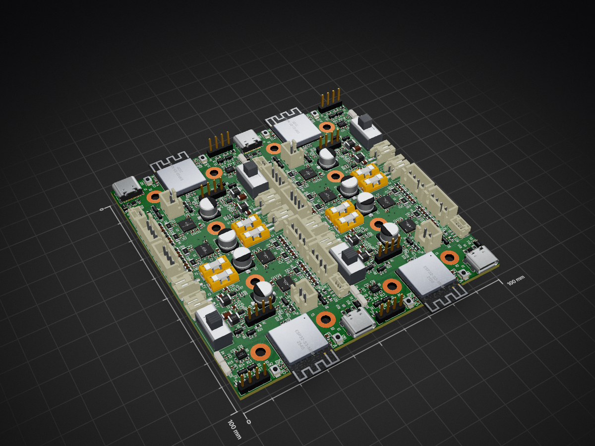
 NEOgHacking/Balancing_cam1
Balancing cam panel is an open-source printed circuit board by NEOgHacking, from the NEOgHacking/Balancing_cam repository on GitHub. It is a 4-layer board of 100 × 100 mm with 580 parts on 127 nets, routed with 2,956 tracks and 848 vias.
It is built around the ESP32-S3-MINI-1-N8, TPS62933DRL and TMC2209-LA, with the LSM6DS3, USBLC6-2P6 and BLM18KG121TN1D among its other parts. Its parts include 184 capacitors, 100 resistors, 56 inductors, 36 diodes and 36 connectors. It belongs with the ESP32 boards of this library.


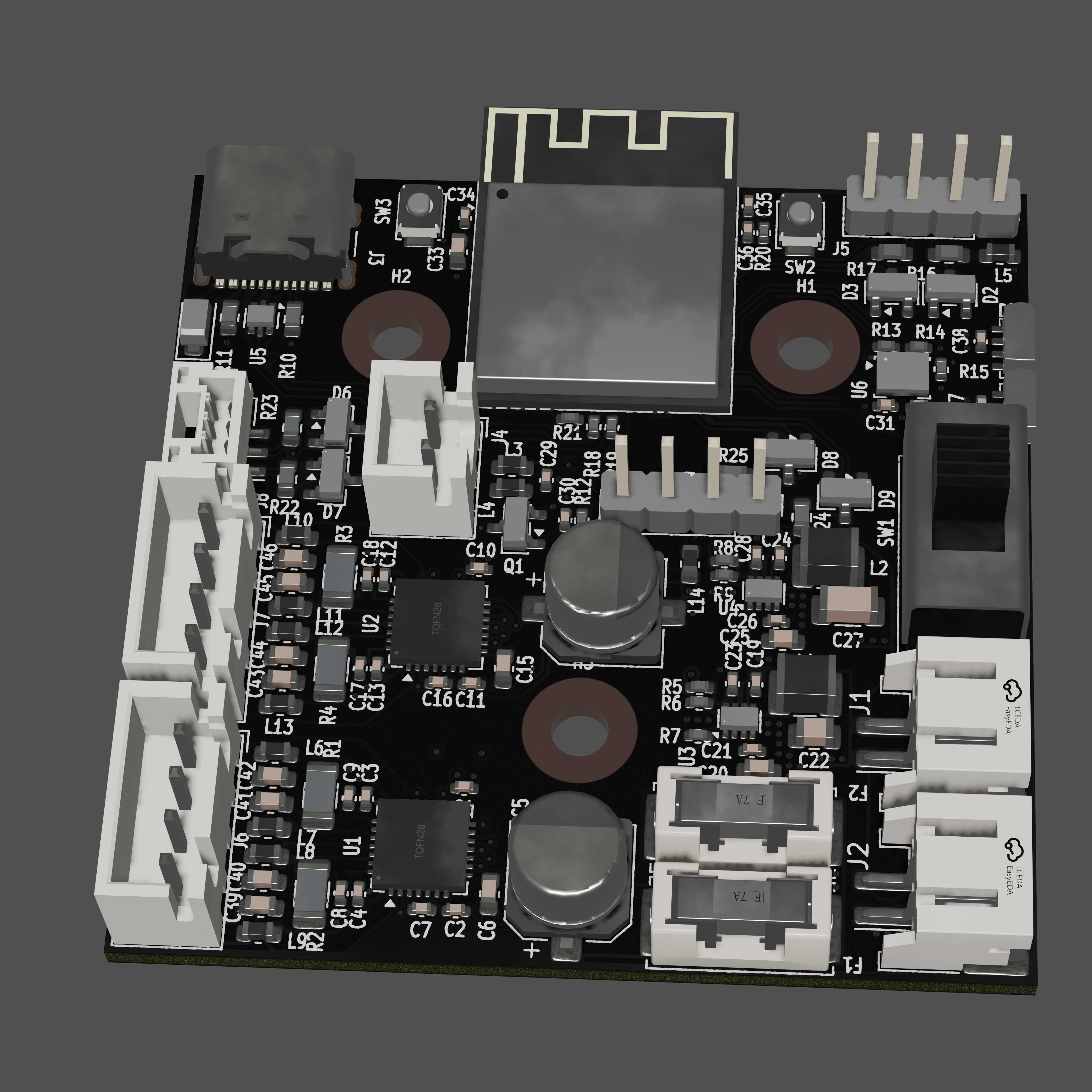
This is a side project to improve on the with a new smaller esd protected pcb to prevent failures on the board, also to make the board smaller and make room for a second battery pack.
| Qty | Value | Footprint | References |
|---|---|---|---|
| 96 | 100n | Capacitor_SMD:C_0402_1005Metric | C1, C1, C1, C1, C10, C10, C10, C10, C11, C11, C11, C11, C12, C12, C12, C12 +80 |
| 88 | TestPoint | TestPoint:TestPoint_Pad_D1.5mm | TP1, TP1, TP1, TP1, TP10, TP10, TP10, TP10, TP11, TP11, TP11, TP11, TP12, TP12, TP12, TP12 +72 |
| 48 | BLM18KG121TN1D | Inductor_SMD:L_0603_1608Metric | L10, L10, L10, L10, L11, L11, L11, L11, L12, L12, L12, L12, L13, L13, L13, L13 +32 |
| 32 | 1n | Capacitor_SMD:C_0603_1608Metric | C39, C39, C39, C39, C40, C40, C40, C40, C41, C41, C41, C41, C42, C42, C42, C42 +16 |
| 24 | 100R | Resistor_SMD:R_0603_1608Metric | R16, R16, R16, R16, R17, R17, R17, R17, R22, R22, R22, R22, R23, R23, R23, R23 +8 |
| 24 | BAV99W | Package_TO_SOT_SMD:SOT-23 | D2, D2, D2, D2, D3, D3, D3, D3, D6, D6, D6, D6, D7, D7, D7, D7 +8 |
| 20 | 10k | Resistor_SMD:R_0402_1005Metric | R6, R6, R6, R6, R13, R13, R13, R13, R14, R14, R14, R14, R20, R20, R20, R20 +4 |
| 16 | 100m | Resistor_SMD:R_1206_3216Metric | R1, R1, R1, R1, R2, R2, R2, R2, R3, R3, R3, R3, R4, R4, R4, R4 |
| 16 | SolderJumper_2_Open | Jumper:SolderJumper-2_P1.3mm_Open_RoundedPad1.0x1.5mm | JP1, JP1, JP1, JP1, JP2, JP2, JP2, JP2, JP3, JP3, JP3, JP3, JP4, JP4, JP4, JP4 |
| 12 | 0R | Resistor_SMD:R_0402_1005Metric | R15, R15, R15, R15, R18, R18, R18, R18, R19, R19, R19, R19 |
| 12 | MountingHole_Pad | MountingHole:MountingHole_3.2mm_M3_Pad | H1, H1, H1, H1, H2, H2, H2, H2, H3, H3, H3, H3 |
| 8 | 100μ | Capacitor_SMD:CP_Elec_6.3x5.4 | C5, C5, C5, C5, C14, C14, C14, C14 |
| 8 | 10u | Capacitor_SMD:C_0603_1608Metric | C20, C20, C20, C20, C25, C25, C25, C25 |
| 8 | 1k | Resistor_SMD:R_0402_1005Metric | R12, R12, R12, R12, R21, R21, R21, R21 |
| 8 | 22n | Capacitor_SMD:C_0402_1005Metric | C7, C7, C7, C7, C16, C16, C16, C16 |
| 8 | 2u2 | Capacitor_SMD:C_0603_1608Metric | C6, C6, C6, C6, C15, C15, C15, C15 |
| 8 | 2u2 | Inductor_SMD:L_1210_3225Metric | L1, L1, L1, L1, L2, L2, L2, L2 |
| 8 | 33n | Capacitor_SMD:C_0402_1005Metric | C23, C23, C23, C23, C28, C28, C28, C28 |
| 8 | 5.1k | Resistor_SMD:R_0603_1608Metric | R10, R10, R10, R10, R11, R11, R11, R11 |
| 8 | B3U-1000P | Button_Switch_SMD:SW_SPST_B3U-1000P | SW2, SW2, SW2, SW2, SW3, SW3, SW3, SW3 |
| 8 | Conn_01x04 | Connector_JST:JST_XH_B4B-XH-A_1x04_P2.50mm_Vertical | J6, J6, J6, J6, J7, J7, J7, J7 |
| 8 | Conn_01x04 | Connector_PinHeader_2.54mm:PinHeader_1x04_P2.54mm_Vertical | J5, J5, J5, J5, J9, J9, J9, J9 |
| 8 | Fuse | Fuse:Fuseholder_Littelfuse_Nano2_154x | F1, F1, F1, F1, F2, F2, F2, F2 |
| 8 | JST_PH | footprints:JST_PH_S2B-PH-SM4-TB_1x02-1MP_P2.00mm_Horizontal | J1, J1, J1, J1, J2, J2, J2, J2 |
| 8 | TMC2209-LA | Package_DFN_QFN:VQFN-28-1EP_5x5mm_P0.5mm_EP3.7x3.7mm_ThermalVias | U1, U1, U1, U1, U2, U2, U2, U2 |
| 8 | TPS62933 | Package_TO_SOT_SMD:SOT-583-8 | U3, U3, U3, U3, U4, U4, U4, U4 |
| 8 | WS2812B-4020 | footprints:WS2812B-4020 | D4, D4, D4, D4, D5, D5, D5, D5 |
| 4 | 100u | Capacitor_SMD:C_1206_3216Metric | C27, C27, C27, C27 |
| 4 | 14k7 | Resistor_SMD:R_0402_1005Metric | R7, R7, R7, R7 |
| 4 | 1u | Capacitor_SMD:C_0402_1005Metric | C36, C36, C36, C36 |
| 4 | 22u | Capacitor_SMD:C_0603_1608Metric | C33, C33, C33, C33 |
| 4 | 30k9 | Resistor_SMD:R_0402_1005Metric | R8, R8, R8, R8 |
| 4 | 47u | Capacitor_SMD:C_0805_2012Metric | C22, C22, C22, C22 |
| 4 | 52k3 | Resistor_SMD:R_0402_1005Metric | R5, R5, R5, R5 |
| 4 | BC817 | Package_TO_SOT_SMD:SOT-23 | Q1, Q1, Q1, Q1 |
| 4 | Conn_01x03 | Connector_JST:JST_GH_BM03B-GHS-TBT_1x03-1MP_P1.25mm_Vertical | J8, J8, J8, J8 |
| 4 | DSK24L | Diode_SMD:D_SOD-123F | D1, D1, D1, D1 |
| 4 | ESP32-S3-MINI-1 | RF_Module:ESP32-S2-MINI-1 | U7, U7, U7, U7 |
| 4 | JST_XH | Connector_JST:JST_XH_B2B-XH-A_1x02_P2.50mm_Vertical | J4, J4, J4, J4 |
| 4 | LSM6DS3 | Package_LGA:LGA-14_3x2.5mm_P0.5mm_LayoutBorder3x4y | U6, U6, U6, U6 |
| 4 | SW_SPDT | footprints:SS12D10G5 | SW1, SW1, SW1, SW1 |
| 4 | USBLC6-2P6 | Package_TO_SOT_SMD:SOT-666 | U5, U5, U5, U5 |
| 4 | USB_C_Receptacle_USB2.0_16P | Connector_USB:USB_C_Receptacle_GCT_USB4105-xx-A_16P_TopMnt_Horizontal | J3, J3, J3, J3 |


NEOgHacking/SCORPION-MAX-V1
4x Power Mosfets for controlling heated beds, heaters, ext.

NEOgHacking/DMXion_4Port_Node
A 4 port dmx node with rdm funtionallity. Connects via ARTNET or sACN


It measures 100 × 100 mm and has 4 copper layers, 1.57 mm thick.
580 parts, built around the ESP32-S3-MINI-1-N8, TPS62933DRL, TMC2209-LA and LSM6DS3. The full list of its parts is on this page, with links to each part's symbol and footprint where PCBKit's library has them.
From the NEOgHacking/Balancing_cam repository on GitHub, at the commit this page was made from: the board is PCB/Balancing_cam/Balancing_cam_panel.kicad_pcb and its schematic PCB/Balancing_cam/Balancing_cam.kicad_sch. PCBKit opens the board in the browser, with nothing to install.
Its repository states no licence, so its author keeps all rights: ask NEOgHacking before reusing the design.