
2 layers50.8 × 20.3 mm
 Multiscale-Metamaterial-Research-Lab/Optics-Table
Documentation for the 'Optics Table' and its development projects
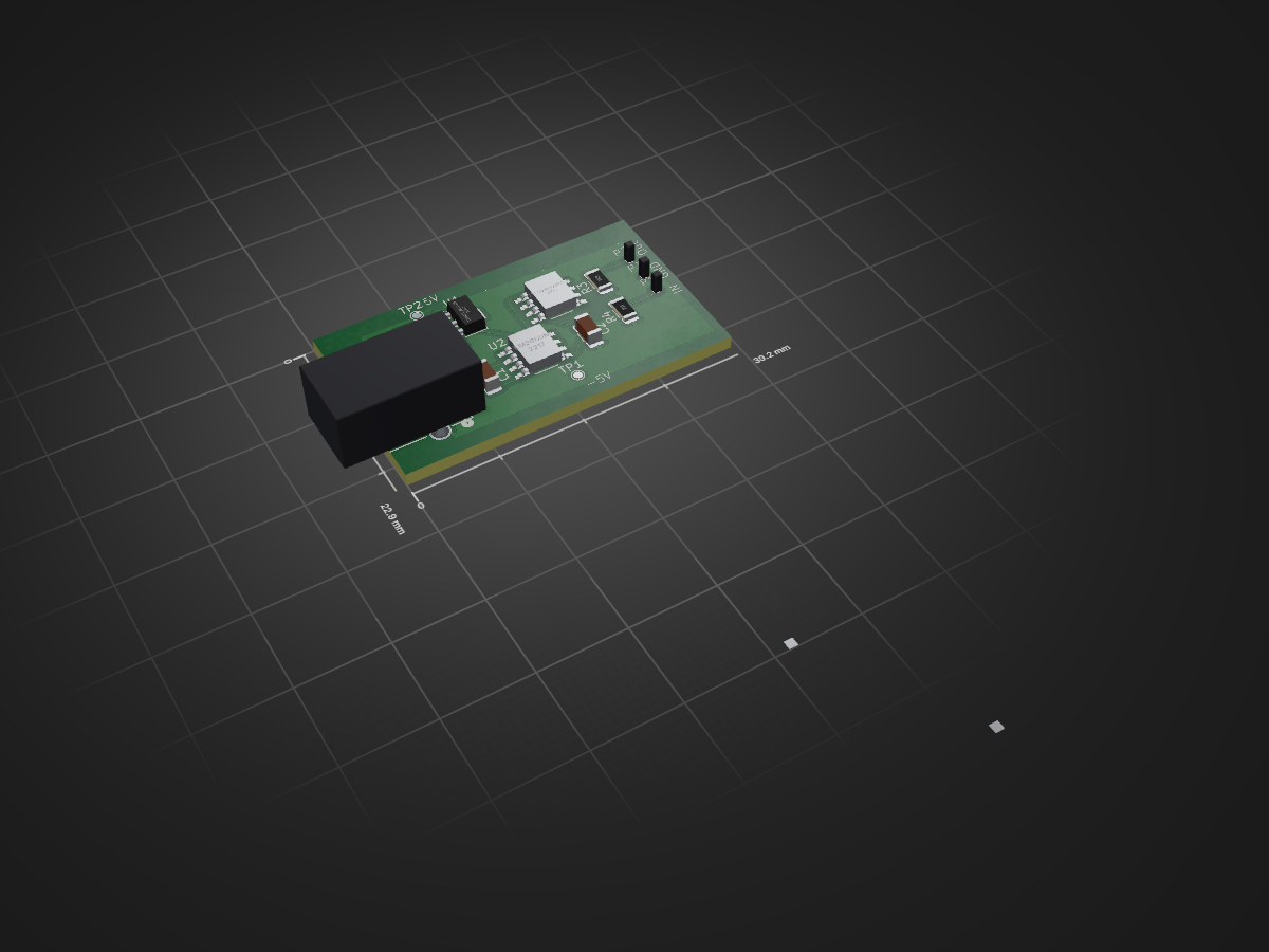
Microwave Reciever is an open-source printed circuit board by Multiscale-Metamaterial-Research-Lab, from the Multiscale-Metamaterial-Research-Lab/Optics-Table repository on GitHub, published under the MIT licence. It is a 2-layer board of 39.2 × 22.9 mm with 15 parts on 14 nets, routed with 51 tracks and 0 vias.
It is built around the LM2660M. Its parts include 4 resistors, 4 connectors, 3 ICs and 2 capacitors. It belongs with the radio and wireless boards of this library.
| Qty | Value | Footprint | References |
|---|---|---|---|
| 2 | 10uf | Capacitor_SMD:C_1206_3216Metric | C1, C2 |
| 2 | R | Resistor_SMD:R_1206_3216Metric | R1, R2 |
| 2 | ~ | PlatedThroughHole_1mm:PlatedThroughHole_1mm | P1, P3 |
| 1 | 100 | Resistor_SMD:R_1206_3216Metric | R4 |
| 1 | 18k | Resistor_SMD:R_1206_3216Metric | R3 |
| 1 | 373 | Adafruit 373 barrel:JACK_373_ADA | J1 |
| 1 | LM2660M | LM2660 (SOIC D_:M08A | U2 |
| 1 | LM317L_SOT-89 | Package_TO_SOT_SMD:SOT-89-3 | U1 |
| 1 | LTC2051HVCS8-PBF | LM2660 (SOIC D_:M08A | U3 |
| 1 | TP +5v | TestPoint:TestPoint_Pad_D1.0mm | TP2 |
| 1 | TP Output | PlatedThroughHole_1mm:PlatedThroughHole_1mm | P2 |
| 1 | TestPoint -5V | TestPoint:TestPoint_Pad_D1.0mm | TP1 |


timohueser/MyoSense
As mentioned before the MyoSense Sensor Modules use dry stainless steel electrodes to pick up the small voltages generated by muscle activity on the skin above the monitored muscle.

google/mozc-devices
Circuit diagrams and firmware source code for Gboard DIY keyboards

hoglet67/RGBtoHDMI
Bare-metal Raspberry Pi project that provides pixel-perfect sampling of Retro Computer RGB/YUV video and conversion to HDMI

mntmn/amiga2000-gfxcard
MNT VA2000, an Open Source Amiga 2/3/4000 Graphics Card (Zorro II/III), written in Verilog

hackclub/OnBoard
💡 Join 1,000 teenagers and make your first PCB with a $100 grant!

kenp-io/not-for-airpods-repairs
The content of this repository is licensed under the WTFPL License. Please have a close look at the terms before using this material.
It measures 39.2 × 22.9 mm and has 2 copper layers, 1.6 mm thick.
15 parts, built around the LM2660M. The full list of its parts is on this page, with links to each part's symbol and footprint where PCBKit's library has them.
From the Multiscale-Metamaterial-Research-Lab/Optics-Table repository on GitHub, at the commit this page was made from: the board is Pasco Transmitter and Receiver Repair/Receiver Files/Design/PCB 8_29_25/Microwave Reciever/Microwave Reciever.kicad_pcb and its schematic Pasco Transmitter and Receiver Repair/Receiver Files/Design/PCB 8_29_25/Microwave Reciever/Microwave Reciever.kicad_sch. PCBKit opens the board in the browser, with nothing to install.
Its repository publishes it under the MIT licence: you may reuse it on that licence's terms (keep the author's notice, and for a copyleft licence share your changes alike).