2 layers82.1 × 22.5 mm
Star pointer
dilshan/star-pointer
DIY virtual electronic finderscope for astronomical telescopes
39 parts24MIT

 MrQuiet7/Rei-32
Minimal STM32 Development Board
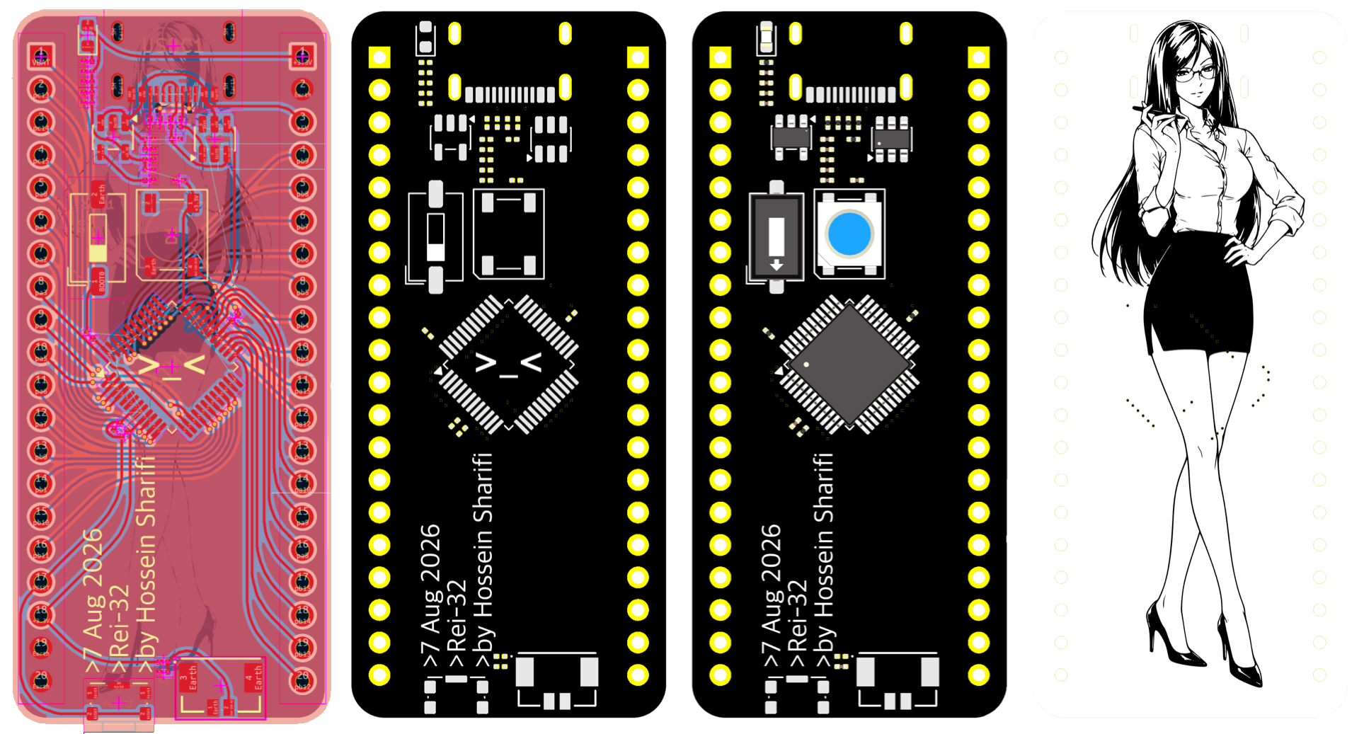
Rei-32 is an open-source printed circuit board by MrQuiet7, from the MrQuiet7/Rei-32 repository on GitHub, published under the GPL-3.0 licence. It is a 2-layer board of 24.6 × 55.2 mm with 34 parts on 56 nets, routed with 359 tracks and 30 vias.
It is built around the RT9193-33GB, USBLC6-2SC6 and WS2812B. Its parts include 12 capacitors, 9 resistors, 2 ICs, 2 diodes and 2 connectors. It belongs with the STM32 boards of this library.



PCB + Front + Front with components + Back
| Qty | Value | Footprint | References |
|---|---|---|---|
| 6 | 104 | Capacitor_SMD:C_0201_0603Metric | C3, C6, C8, C9, C10, C11 |
| 2 | 100nf | Capacitor_SMD:C_0201_0603Metric | C7, C12 |
| 2 | 105 | Capacitor_SMD:C_0201_0603Metric | C1, C2 |
| 2 | 10K | Resistor_SMD:R_0201_0603Metric | R1, R9 |
| 2 | 20 | Resistor_SMD:R_0201_0603Metric | R4, R5 |
| 2 | 5.1K | Resistor_SMD:R_0201_0603Metric | R2, R3 |
| 2 | PINHD_1x20_Female | Connector_PinSocket_2.54mm:PinSocket_1x20_P2.54mm_Vertical | P1, p2 |
| 1 | 106 | Capacitor_SMD:C_0201_0603Metric | C5 |
| 1 | 1N5817 | Diode_SMD:D_0201_0603Metric | D2 |
| 1 | 223 | Capacitor_SMD:C_0201_0603Metric | C4 |
| 1 | 330 | Resistor_SMD:R_0201_0603Metric | R8 |
| 1 | 4.7K | Resistor_SMD:R_0201_0603Metric | R6 |
| 1 | 510 | Resistor_SMD:R_0201_0603Metric | R7 |
| 1 | LED | LED_SMD:LED_0603_1608Metric | power1 |
| 1 | LOGO | LOGO | G*** |
| 1 | REST | Button_Switch_SMD:SW_SPST_CK_KMS2xxG | reset1 |
| 1 | RT9193-33 | Package_TO_SOT_SMD:TSOT-23-5 | U1 |
| 1 | STM32F103C8Tx | Package_QFP:LQFP-48_7x7mm_P0.5mm | STM1 |
| 1 | SW_Push | Button_Switch_SMD:SW_DIP_SPSTx01_Slide_6.7x4.1mm_W6.73mm_P2.54mm_LowProfile_JPin | boot1 |
| 1 | USBLC6-2SC6 | Package_TO_SOT_SMD:SOT-23-6 | U2 |
| 1 | USB_C_Receptacle_USB2.0_16P | Connector_USB:USB_C_Receptacle_G-Switch_GT-USB-7010ASV | USBC1 |
| 1 | WS2812B | LED_SMD:LED_WS2812B_PLCC4_5.0x5.0mm_P3.2mm | D1 |
| 1 | ~ | RTC_Battrey:CONN_505568_02_MOL | RTC1 |
dilshan/star-pointer
DIY virtual electronic finderscope for astronomical telescopes

Ahmedsaid5911/Universal-USB-to-Can-UART-I2C-Converter
USB to UART interface (up to 2 UART ports)


YeetTheAnson/RFly-One
Offline general aviation proximity awareness system with support for ADS-B, FLARM AIR V7, OGNTP and FANET+


havrak/UAV-project
Building a UAV as part of my final year on high school, now my hobby project
It measures 24.6 × 55.2 mm and has 2 copper layers, 1.6 mm thick.
34 parts, built around the RT9193-33GB, USBLC6-2SC6 and WS2812B. The full list of its parts is on this page, with links to each part's symbol and footprint where PCBKit's library has them.
From the MrQuiet7/Rei-32 repository on GitHub, at the commit this page was made from: the board is Hardware/Rei-32.kicad_pcb and its schematic Hardware/Rei-32.kicad_sch. PCBKit opens the board in the browser, with nothing to install.
Its repository publishes it under the GPL-3.0 licence: you may reuse it on that licence's terms (keep the author's notice, and for a copyleft licence share your changes alike).