4 layers150 × 50 mm

 Mounith-H/Portable_temperature_sensor
wireless IoT temperature monitoring device based on the ESP8266 NodeMCU platform. It uses a MAX6675 thermocouple interface to measure temperatures up to 1024°C with high precision, making it suitable for industrial monitoring, cooking, 3D printing, and scientific applications.
Portable temperature sensor is an open-source printed circuit board by Mounith-H, from the Mounith-H/Portable_temperature_sensor repository on GitHub, published under the MIT licence. It is a 2-layer board of 48.5 × 50.4 mm with 17 parts on 22 nets, routed with 103 tracks and 0 vias.
It is built around the WEMOS D1 MINI and MAX6675ISA+T. Its parts include 5 capacitors, 4 resistors, 4 connectors, 2 ICs and 1 transistor. It belongs with the sensors and measurement and home automation and IoT boards and the ESP8266 boards of this library.


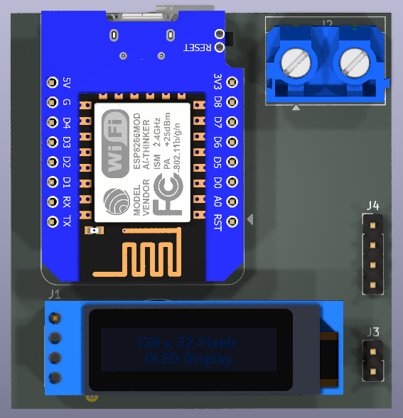

The Portable Temperature Sensor is a wireless IoT temperature monitoring device based on the ESP8266 NodeMCU platform. It uses a MAX6675 thermocouple interface to measure temperatures up to 1024°C with high precision, making it suitable for industrial monitoring, cooking, 3D printing, and scientific applications.
| Pin Numbers | Pin Names | Pin Function | Other | Connection |
|---|---|---|---|---|
| ADC0 | A0 | Analog Input | X | X |
| GPIO16 | D0 | WAKE | X | SEN-CS |
| GPIO5 | D1 | SCL | X | OLED/ SCL |
| GPIO4 | D2 | SDA | X | OLED/ SDA |
| GPIO0 | D3 | FLASH | Pull-up | BUZZER |
| GPIO2 | D4 | TXD1/LED | Pull-up | INTERRUPT |
| GPIO14 | D5 | SCLK | X | SEN-SCK |
| GPIO12 | D6 | MISO | X | SEN-SO |
| GPIO13 | D7 | MOSI/RXD2 | X | UART-RX |
| GPIO15 | D8 | CS/TXD2 | Pull-down | UART-TX |
| GPIO3 | RX | RXD0 | X | X |
| GPIO1 | TX | TXD0 | X | X |
| RST | RST | Reset | Pull-up | X |
Clone this repository:
git clone https://github.com/MOUNITH-H/Portable_temperature_sensor.gitOpen the project in PlatformIO or Arduino IDE:
Portable_temperature_sensor foldersrc/main.cpp as your sketchConfigure WiFi and MQTT settings:
main.cppBuild and upload to your NodeMCU
The project includes a custom PCB design created with KiCad. The design files are in the pcb folder:
pcb.kicad_schpcb.kicad_pcbpcb/bom/ibom.htmlportable_temp_sensor/temperatureportable_temp_sensor/settings| Topic | Description | Message Format |
|---|---|---|
portable_temp_sensor/temperature | Current temperature readings | {"temp": 25.4, "timestamp": 1620123456} |
portable_temp_sensor/settings | Device configuration | {"threshold": 80, "buzzer_enabled": true} |
portable_temp_sensor/status | Device status information | {"uptime": 3600, "wifi_strength": -67} |
Contributions are welcome! Please feel free to submit a Pull Request.
This project is licensed under the MIT License - see the LICENSE file for details.
| Qty | Value | Footprint | References |
|---|---|---|---|
| 5 | 0.1uf | Capacitor_SMD:C_1206_3216Metric_Pad1.33x1.80mm_HandSolder | C5, C6, C7, C8, C9 |
| 1 | 100R | Resistor_THT:R_Axial_DIN0207_L6.3mm_D2.5mm_P10.16mm_Horizontal | R4 |
| 1 | 10k | Resistor_THT:R_Axial_DIN0207_L6.3mm_D2.5mm_P10.16mm_Horizontal | R1 |
| 1 | 10k | Resistor_SMD:R_1206_3216Metric_Pad1.30x1.75mm_HandSolder | R2 |
| 1 | 1k | Resistor_SMD:R_1206_3216Metric_Pad1.30x1.75mm_HandSolder | R3 |
| 1 | Buzzer_5V | Buzzer_Beeper:Buzzer_12x9.5RM7.6 | BZ1 |
| 1 | Interupt | Connector_PinHeader_2.54mm:PinHeader_1x02_P2.54mm_Vertical | J3 |
| 1 | MAX6675ISA_ | Snapeda:MAX6675ISA__SOIC127P600X175-8N | U2 |
| 1 | NPN | Package_TO_SOT_SMD:SOT-23-3 | Q1 |
| 1 | OLED | Connector_PinSocket_2.54mm:PinSocket_1x04_P2.54mm_Vertical | J1 |
| 1 | Thermocouple | TerminalBlock_MetzConnect:TerminalBlock_MetzConnect_Type175_RT02702HBLC_1x02_P7.50mm_Horizontal | J2 |
| 1 | UART | Connector_PinHeader_2.54mm:PinHeader_1x04_P2.54mm_Vertical | J4 |
| 1 | WEMOS_D1_mini | RF_Module:WEMOS_D1_mini_light | U5 |

Markuselectronics/DIY-USB-C-Reflow-Hotplate
A compact, open-source DIY Reflow Hotplate powered by USB-C PD and STM32. Features a custom aluminum PCB heater, OLED display, and PID temperature control for portable SMD soldering.


Sensei82013/Reflow-Oven
STM32F103 reflow oven controller: K-type thermocouple via MAX6675, 160 W element through a solid state relay, on-MCU PI loop, browser UI over SWD, and a 7in Nextion panel in progress.

SimonDaniel605/Hydrogel-3D-Printer
Development of a custom hydrogel 3D printer for tissue engineering and research applications for Stellenbosch University.

uob-hep-cad/dune_timing_system_gib_slow_control_d001-25_dga
Slow Control Interface Board for the DUNE Timing System GIB

nkitanov/iaq_board
IAQ Board is a DIY (Do-It-Yourself) device for measuring internal air quality

bitfixer/bf-romulator
Romulator - RAM/ROM replacement and debug for 6502 CPU systems
It measures 48.5 × 50.4 mm and has 2 copper layers, 1.6 mm thick.
17 parts, built around the WEMOS D1 MINI and MAX6675ISA+T. The full list of its parts is on this page, with links to each part's symbol and footprint where PCBKit's library has them.
From the Mounith-H/Portable_temperature_sensor repository on GitHub, at the commit this page was made from: the board is pcb/pcb.kicad_pcb and its schematic pcb/pcb.kicad_sch. PCBKit opens the board in the browser, with nothing to install.
Its repository publishes it under the MIT licence: you may reuse it on that licence's terms (keep the author's notice, and for a copyleft licence share your changes alike).