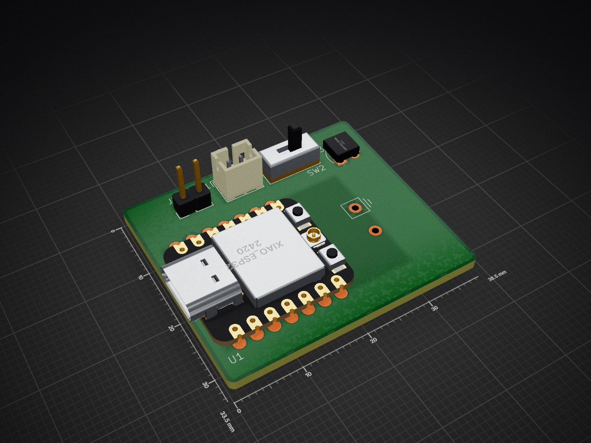
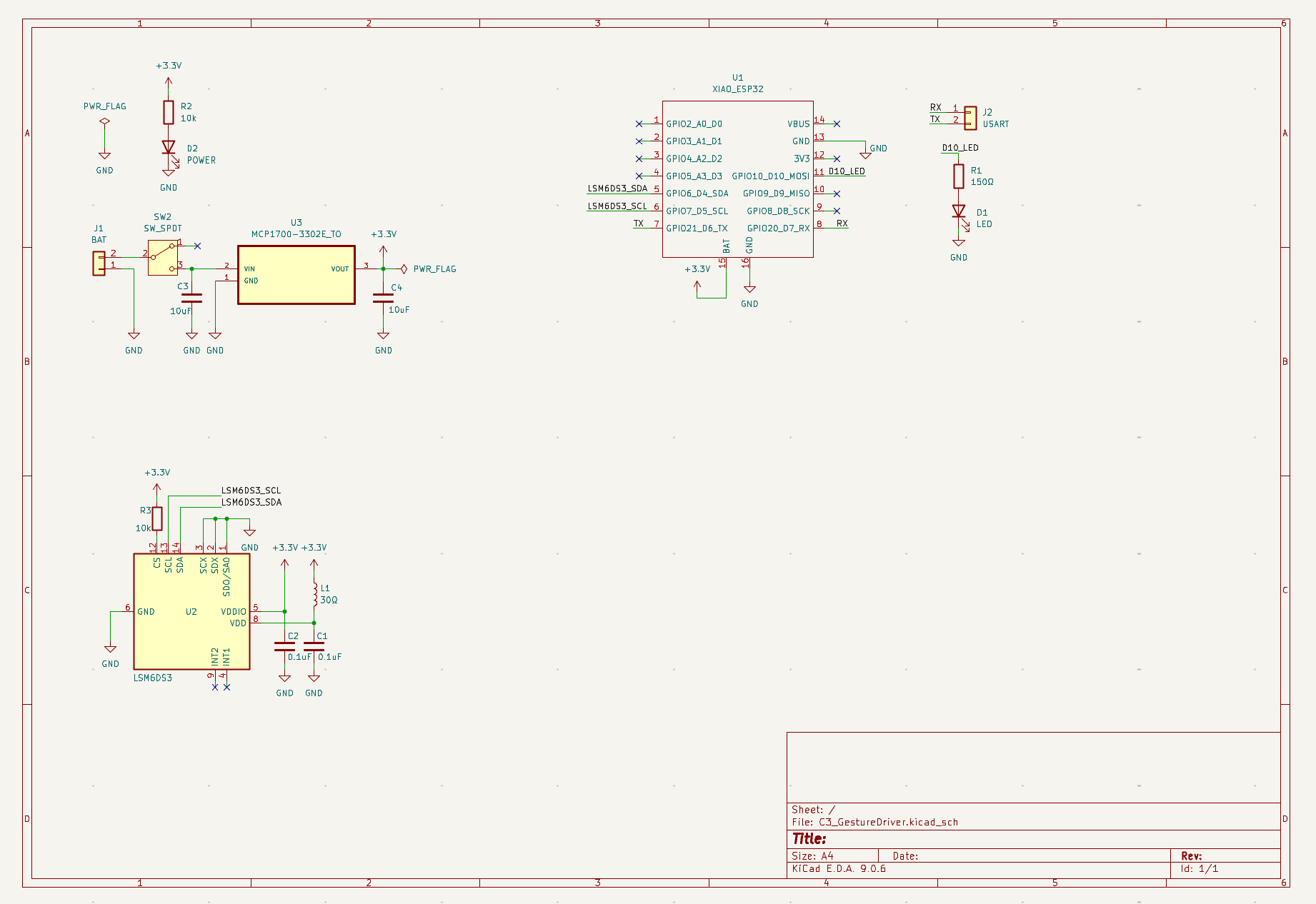
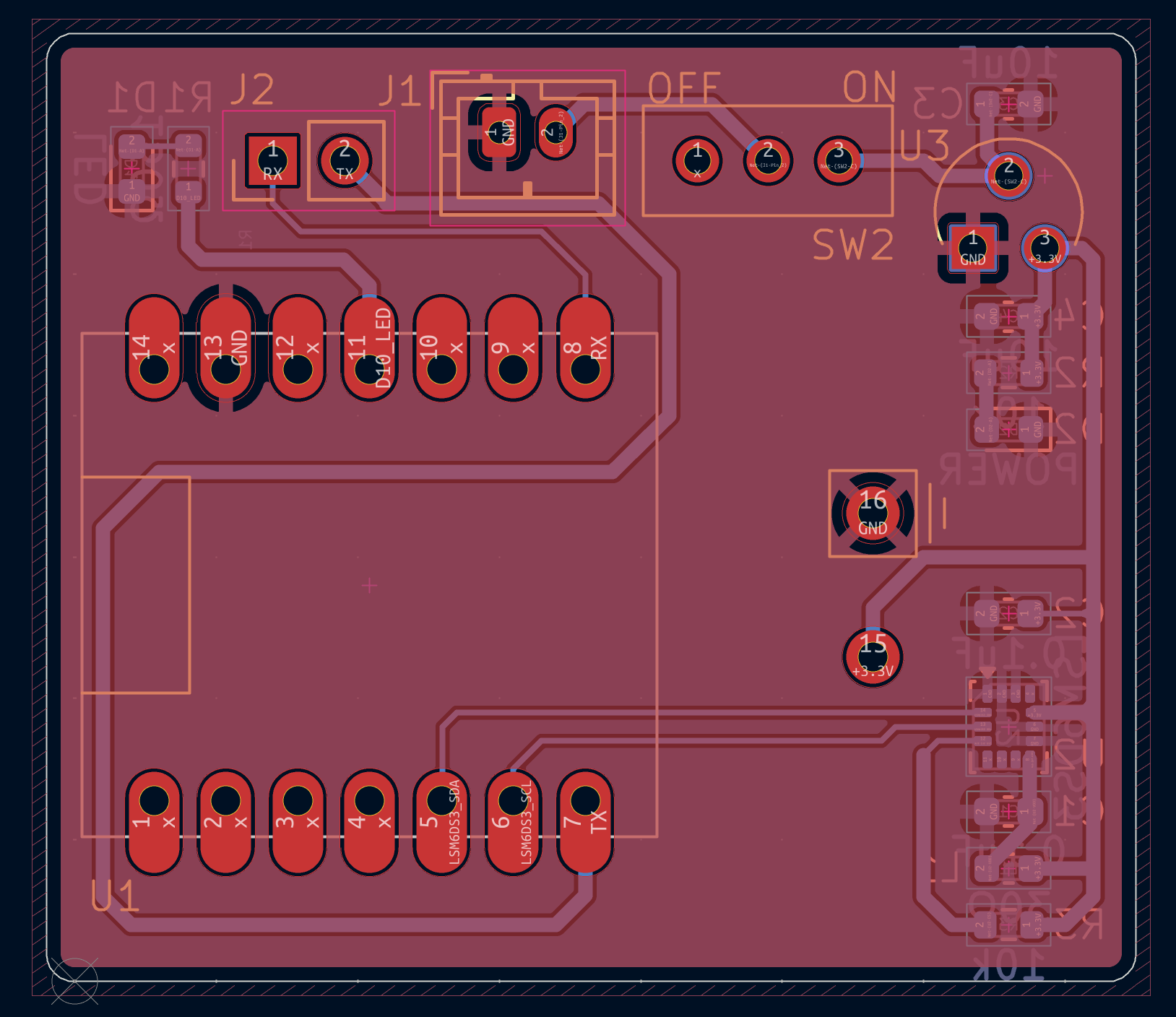
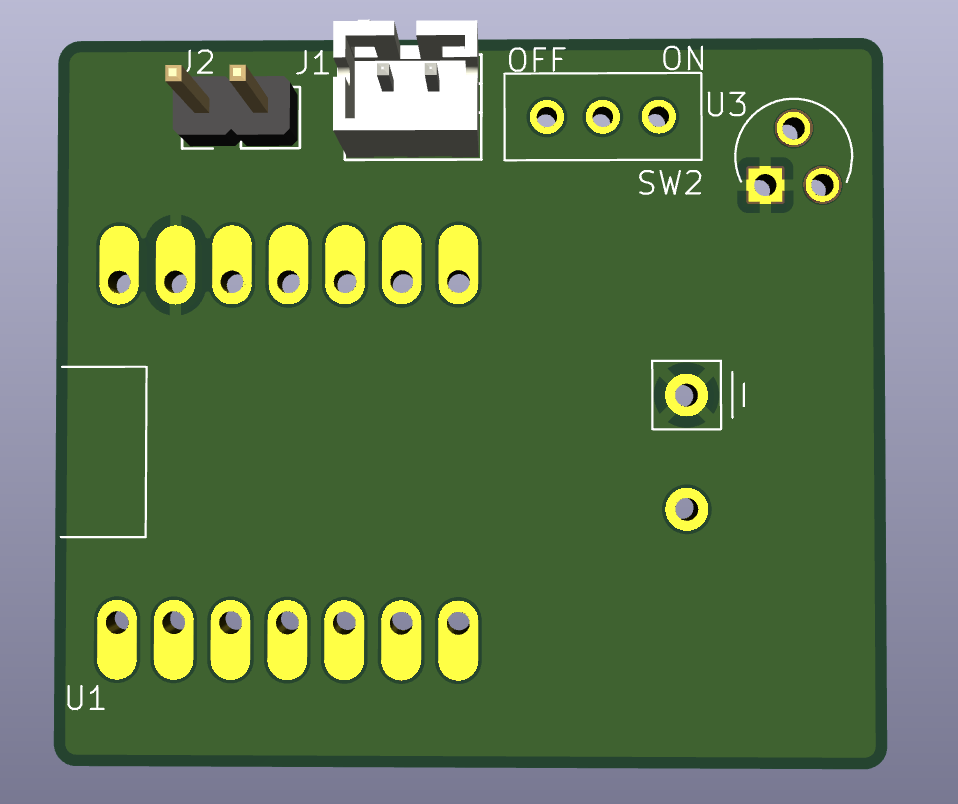
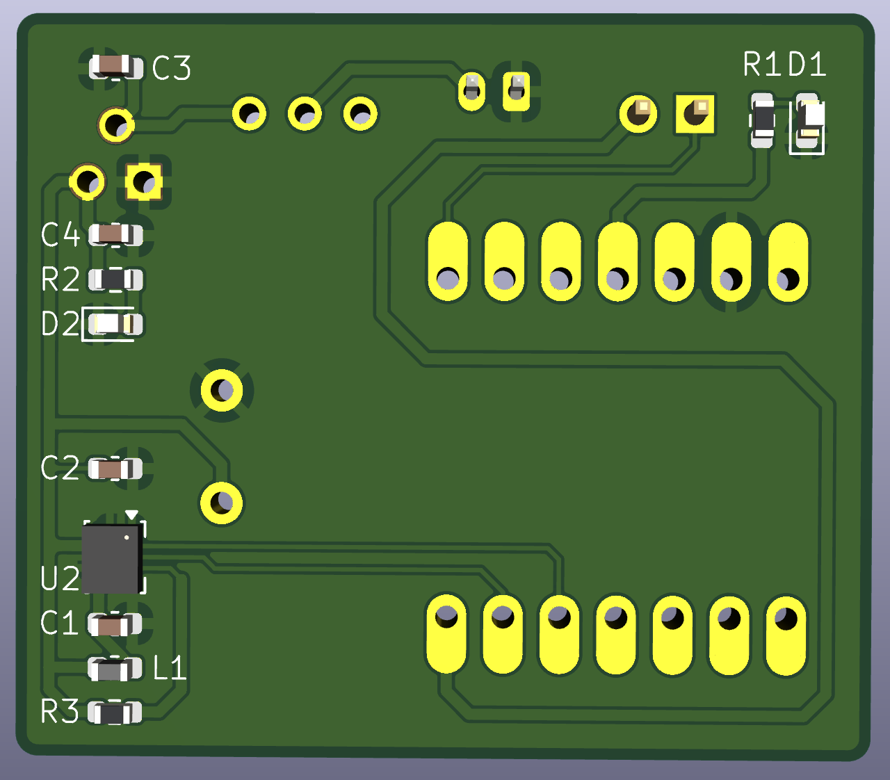
C3 GestureDriver is an open-source printed circuit board by MengqiS21, from the MengqiS21/TECHIN514_FinalProject repository on GitHub. It is a 2-layer board of 38.5 × 33.5 mm with 16 parts on 26 nets, routed with 80 tracks and 0 vias.
It is built around the LSM6DS3, MCP1700-3302E/TO and XIAO ESP32C3. Its parts include 4 capacitors, 3 resistors, 3 ICs, 2 diodes and 2 connectors. It belongs with the ESP32 and RISC-V boards of this library.
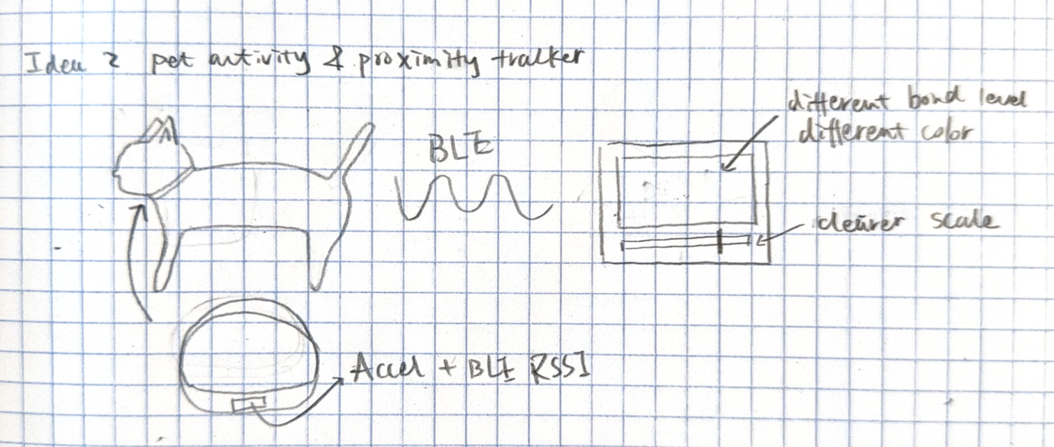
A wearable sensing tag for pets and a tabletop display that visualizes daily activity and proximity-based companionship.
The system is designed as a calm, ambient tool that supports reflection rather than real-time alerts, helping pet owners understand patterns of activity and togetherness over the course of a day. By translating sensed data into a physical gauge, the project emphasizes presence and routine over precise tracking or notifications.
1. Overview
What it does
This project consists of a lightweight sensing device attached to a pet’s collar and a tabletop display device placed in the home. The system tracks the pet’s activity level and estimates proximity to the owner throughout the day, visualizing overall “bond time” using a physical gauge instead of a screen.
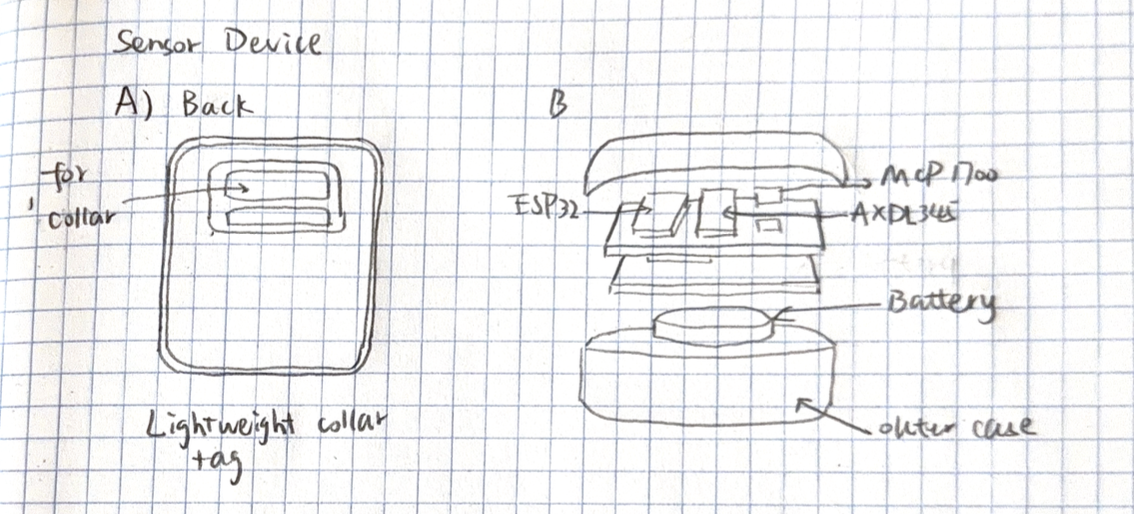
The sensing device is a lightweight tag mounted on a pet’s collar that detects motion and estimates proximity to the owner. It classifies activity levels (resting, walking, high activity) and tracks how much time the pet spends near the display device without using GPS.
Detailed sensing device sketch
How it works
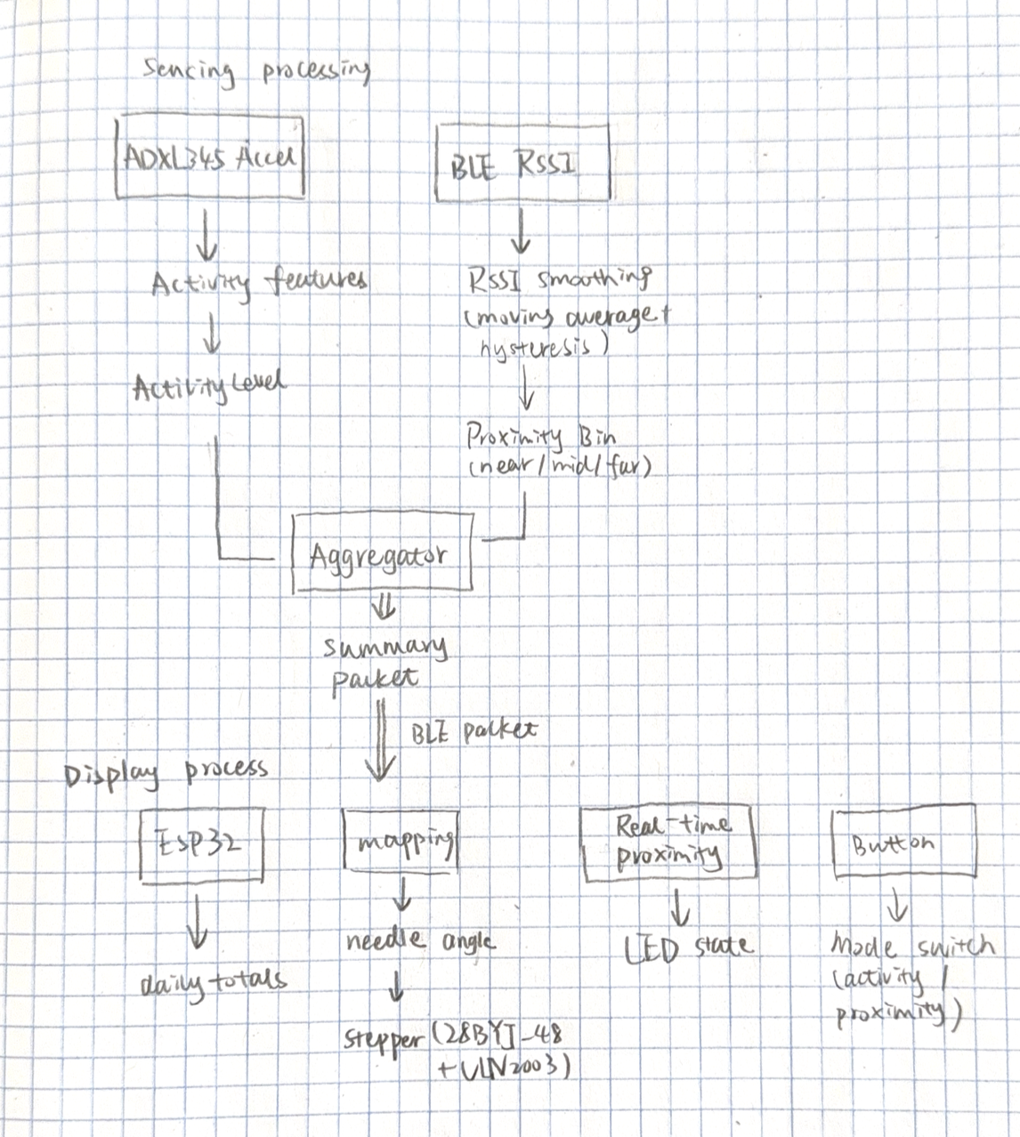
An onboard accelerometer detects motion patterns to estimate activity intensity.
The sensor samples IMU acceleration for a short time window and computes a compact activity score.
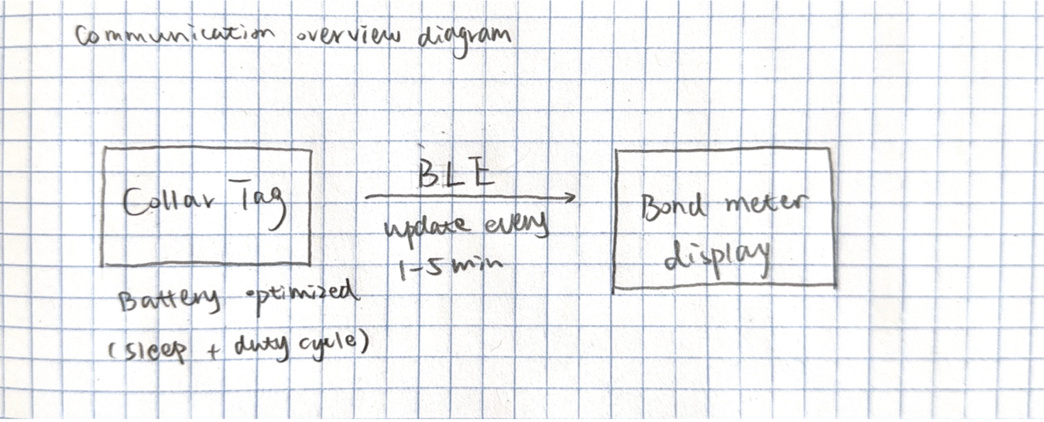
Summarized data is transmitted periodically to the display device via BLE.
Signal Processing / Machine Learning (Current Implementation)
The current system uses lightweight signal processing, not a trained machine learning model.
In firmware/sensor_tag/src/main.cpp, the tag samples acceleration for a 1.5 s window with a 40 ms sample period.
For each sample, it computes motion magnitude proxy |ax| + |ay| + |az|, averages over the window, and maps it linearly to a 0-100 activity score (3g -> 100, clamped).
This activity score is sent to the display via BLE and mapped to motor/LED behavior.
Accuracy Numbers (Current Status)
A labeled dataset evaluation is not yet included in this repository.
Therefore, formal ML metrics such as accuracy / precision / recall / F1 are currently N/A (not reported yet).
Sensors and components (with part numbers)
Accelerometer: ADXL345 (Analog Devices, 3-axis digital accelerometer)
Microcontroller + BLE: ESP32-C3-MINI-1
Battery: CR2032 coin cell or 150–300 mAh LiPo battery
Power management: MCP1700 low-dropout regulator
Optional proximity aid: Onboard ESP32 BLE RSSI (no extra sensor required)
3. Display Device (Bond Meter)
Description
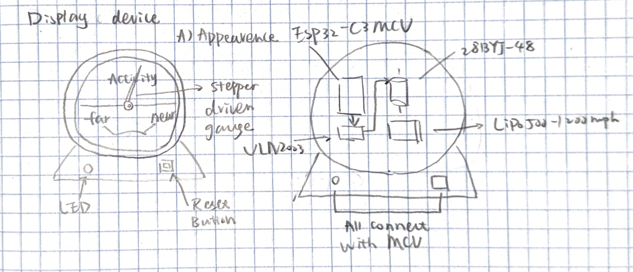
The display device is a tabletop “bond meter” that physically visualizes the pet’s daily activity and proximity time using a stepper-motor-driven gauge needle. An LED provides real-time feedback when the pet is nearby, and a button allows users to switch display modes or acknowledge the status.
Detailed display device sketch
How it works
The display receives summarized activity and proximity data via BLE.
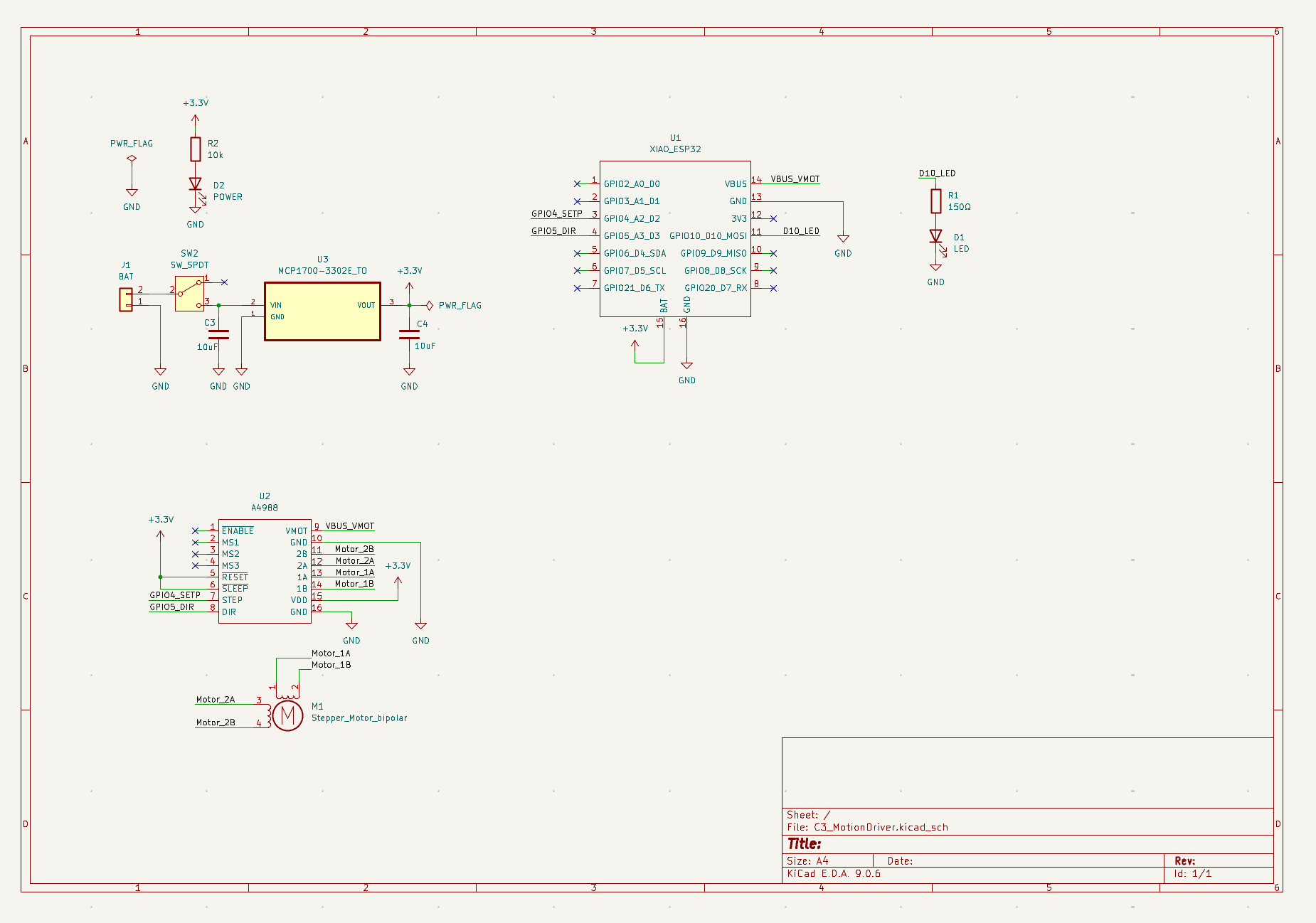
The microcontroller maps daily totals to a gauge needle position using a stepper motor.
The LED indicates current proximity state (e.g., pet nearby vs away).
The button toggles display modes (activity vs proximity) or resets daily tracking.
Components (with part numbers)
Microcontroller + BLE: ESP32-C3-MINI-1
Stepper motor: 28BYJ-48 stepper motor
Motor driver: ULN2003 stepper driver
LED: WS2812B single RGB LED or standard 5mm LED
Button: Standard tact switch
Battery: 500–1200 mAh LiPo battery
4. System Communication & Data Flow
Wireless communication overview
Detailed system diagram
Notes on Power and Feasibility
Both devices are battery-powered and optimized for low-duty-cycle operation. The sensing device minimizes power usage through aggressive sleep scheduling, while the display device uses short stepper motor movements and infrequent updates to maintain reasonable battery life.
Vehicle engine faults such as air leaks, ignition misfires, and abnormal idle behavior often produce characteristic acoustic signatures that trained mechanics can identify by ear.
This project combines the NES, SNES, N64 and Genesis DaemonBite Retro Controllers projects together with a custom PCB to support 4 different controllers with a single socketed Arduino Pro Micro.
It measures 38.5 × 33.5 mm and has 2 copper layers, 1.6 mm thick.
What parts does the C3 GestureDriver use?
16 parts, built around the LSM6DS3, MCP1700-3302E/TO and XIAO ESP32C3. The full list of its parts is on this page, with links to each part's symbol and footprint where PCBKit's library has them.
Where can I download the C3 GestureDriver KiCad files?
From the MengqiS21/TECHIN514_FinalProject repository on GitHub, at the commit this page was made from: the board is hardware/pcb/sensor_tag/C3_GestureDriver.kicad_pcb and its schematic hardware/pcb/display/C3_MotionDriver.kicad_sch. PCBKit opens the board in the browser, with nothing to install.
Can I use the C3 GestureDriver design in my own project?
Its repository states no licence, so its author keeps all rights: ask MengqiS21 before reusing the design.