

2 layers45 × 85 mm
GPSBoard
MatthewBoeding/GPSboard
Lab 2 for ECEN-435 design files. Will update as necessary.
17 parts1BSD-3-Clause
 MatthewBoeding/GPSboard1
Lab 2 for ECEN-435 design files. Will update as necessary.
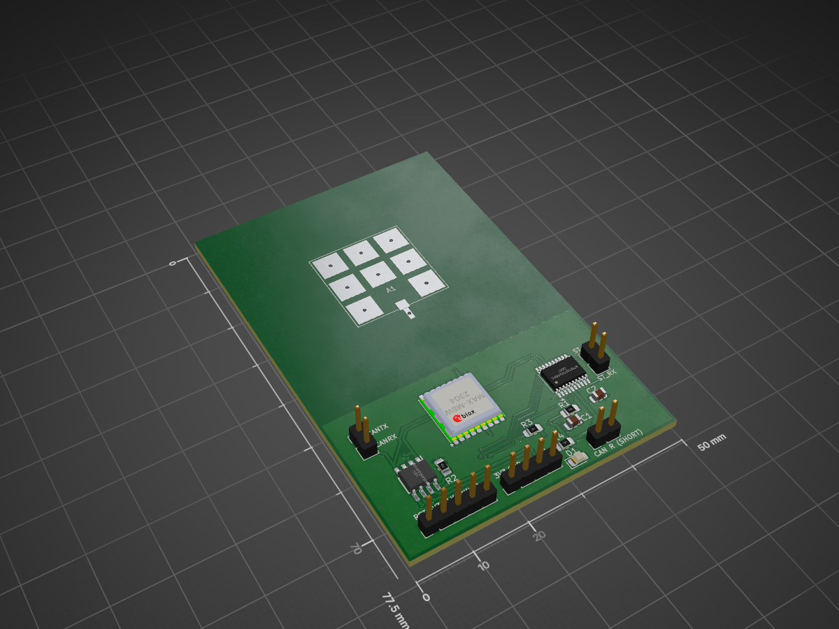
GPS board v3 is an open-source printed circuit board by MatthewBoeding, from the MatthewBoeding/GPSboard repository on GitHub, published under the BSD-3-Clause licence. It is a 2-layer board of 50 × 77.5 mm with 17 parts on 32 nets, routed with 152 tracks and 37 vias.
It is built around the MAX-M8W-0 and SN65HVD231QDRQ1. Its parts include 5 connectors, 4 resistors, 3 ICs, 2 capacitors and 1 diode. It belongs with the radio and wireless boards and the STM32 boards of this library.
This board was designed for ECEN-4350 at the University of Nebraska-Lincoln (Scott Campus), so I will not be updating once completed. If a new design is required in the future, I will place it here. R1-R3 = 1kΩ, L2 = 5.6nH, C1 = 0Ω, C2 = 1.8 pF, C3 = 1µF
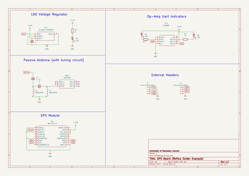
Version 1.0 board had issues with CAN communication. If this design is reused, will need to add on an LDO and allow for 5.0V to troubleshoot CAN transmission errors.
| Qty | Value | Footprint | References |
|---|---|---|---|
| 2 | .1uF | Capacitor_SMD:C_0805_2012Metric | C1, C2 |
| 2 | 10k | Resistor_SMD:R_0805_2012Metric_Pad1.20x1.40mm_HandSolder | R1, R2 |
| 2 | 120R | Resistor_SMD:R_0805_2012Metric_Pad1.20x1.40mm_HandSolder | R3, R4 |
| 2 | STM-UART | Connector_PinHeader_2.54mm:PinHeader_1x02_P2.54mm_Vertical | J1, J5 |
| 1 | LED_Green | LED_SMD:LED_0805_2012Metric_Pad1.15x1.40mm_HandSolder | D1 |
| 1 | LOGO | Graphics:signiture | G*** |
| 1 | MAX-M8W | RF_GPS:ublox_MAX | U5 |
| 1 | SN65HVD231QDR | Package_SO:SOIC127P600X175-8N | IC2 |
| 1 | STM32F042F4Px | Package_SO:TSSOP-20_4.4x6.5mm_P0.65mm | U1 |
| 1 | ~ | RF_Antenna:L000953-01 | A1 |
| 1 | ~ | Connector_PinHeader_2.54mm:PinHeader_1x04_P2.54mm_Vertical | J3 |
| 1 | ~ | Connector_PinHeader_2.54mm:PinHeader_1x05_P2.54mm_Vertical | J4 |
| 1 | ~ | Connector_PinHeader_2.54mm:PinHeader_1x02_P2.54mm_Vertical | J2 |
MatthewBoeding/GPSboard
Lab 2 for ECEN-435 design files. Will update as necessary.

osmocom/osmo-e1-hardware
Osmocom open source E1 (TDM) hardware; mirror of https://gitea.osmocom.org/retronetworking/osmo-e1-hardware

mkrasselt1/obd32
Anyone is free to join our goal to make the hardware reliable and affordable.

Momozavur/CANnode2
Open the appropriate .kicadpro file in KiCad; .pro entries are legacy projects. Keep schematics, boards, local libraries, library tables, and supporting files together.

Momozavur/CANPCB
Open the appropriate .kicadpro file in KiCad; .pro entries are legacy projects. Keep schematics, boards, local libraries, library tables, and supporting files together.

Momozavur/STM32G474RET6-Isolated-V0
KiCad design files for STM32G474RET6 Isolated V0.


It measures 50 × 77.5 mm and has 2 copper layers, 1.6 mm thick.
17 parts, built around the MAX-M8W-0 and SN65HVD231QDRQ1. The full list of its parts is on this page, with links to each part's symbol and footprint where PCBKit's library has them.
From the MatthewBoeding/GPSboard repository on GitHub, at the commit this page was made from: the board is Hardware Design/GPS_board_v3.kicad_pcb and its schematic Hardware Design/GPS_board_v3.kicad_sch. PCBKit opens the board in the browser, with nothing to install.
Its repository publishes it under the BSD-3-Clause licence: you may reuse it on that licence's terms (keep the author's notice, and for a copyleft licence share your changes alike).