2 layers90 × 67 mm

 Manawyrm/ATAPIMega19
Standalone (P)ATA/ATAPI CD Player
ATAPIMega is an open-source printed circuit board by Manawyrm, from the Manawyrm/ATAPIMega repository on GitHub, published under the GPL-3.0 licence. It is a 4-layer board of 100 × 100 mm with 59 parts on 133 nets, routed with 791 tracks and 326 vias.
It is built around the ATMEGA2560-16AU and SY8113BADC. Its parts include 15 capacitors, 12 resistors, 9 connectors, 7 switches and 3 ICs. It belongs with the retro computing and games boards and the AVR (ATmega, ATtiny) boards of this library.


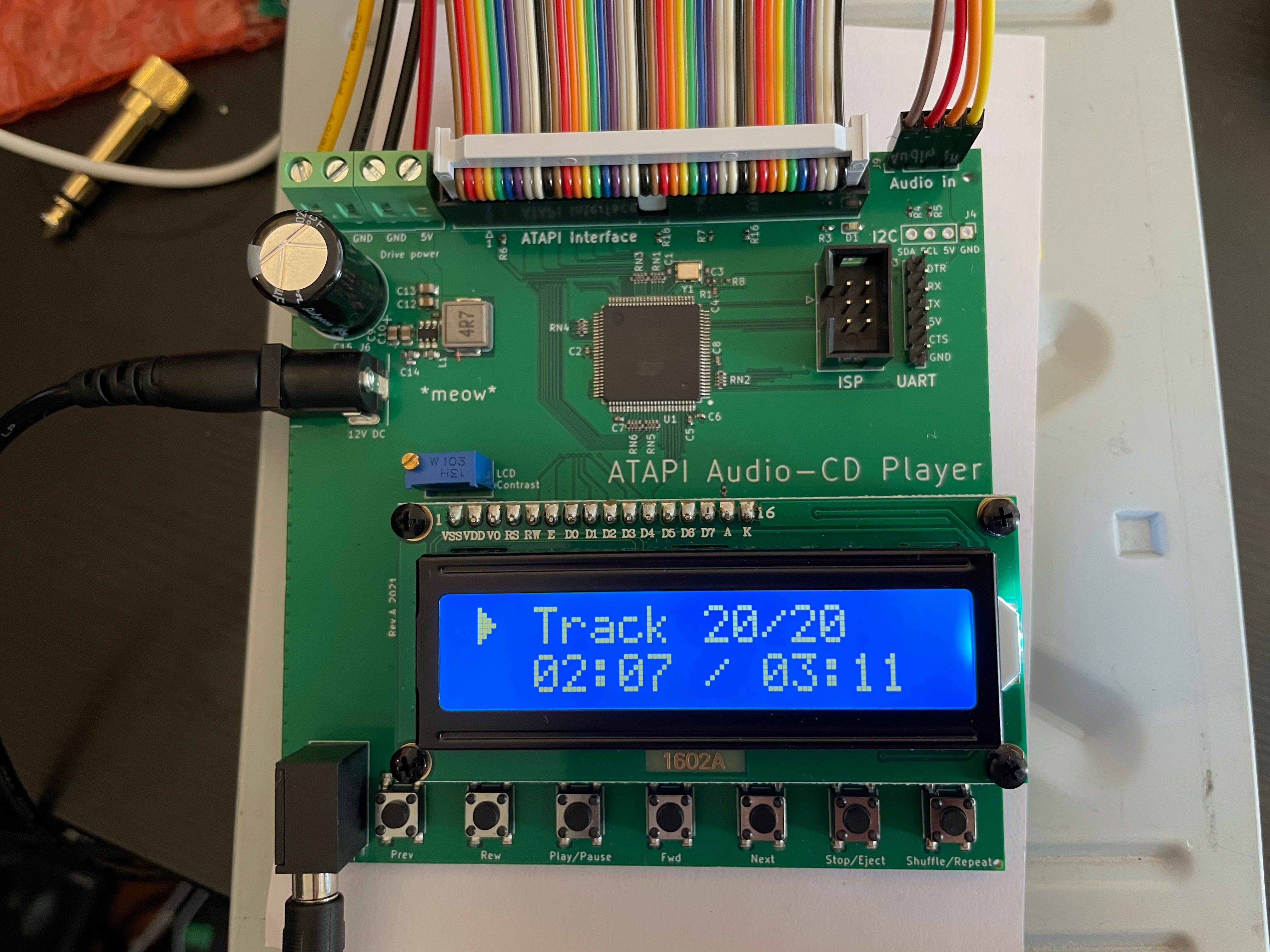
ATAPIMega is a hardware project which allows regular (P)ATA CD/DVD drives to be used as a standalone Audio-CD player.
This repository contains KiCAD PCB design and schematic for the CD player.
The PCB accepts (regulated!) 12V DC power via a 5.5mm/2.1mm barrel jack and outputs 12V/5V for the CD drive.
The microcontroller is an ATmega2560 (Arduino Mega-compatible), chosen for 5V-I/O voltage and high pin-count (and bad availability of STM32's in the component shortage of 2021).
The PCB can be fully assembled at JLCPCBs assembly service, including through-hole parts. Only the LCD will have to be installed manually.
Manufacturing files for automatic assembly service can be found at gerbers/RevA/ATAPIMega/.
Due to the high amount of extended components, setup fees are quite high (~30$).
Price will decrease significantly with higher board count (~15$/board).
Schematic
Interactive BOM
Firmware
Rev.A: FTDI / UART connector reset circuitry is wrong, needs bodge resistor!
5V Step-Down switch-mode regulator was designed with a lot of help from @Toble_Miner! Thanks!
| Qty | Value | Footprint | References |
|---|---|---|---|
| 7 | 100nF | Capacitor_SMD:C_0402_1005Metric | C2, C4, C5, C6, C7, C8, C11 |
| 6 | 33R | Resistor_SMD:R_Array_Convex_4x0402 | RN1, RN2, RN3, RN4, RN5, RN6 |
| 5 | 10k | Resistor_SMD:R_0402_1005Metric | R1, R6, R7, R16, R18 |
| 4 | 22uF | Capacitor_SMD:C_0805_2012Metric | C9, C10, C12, C13 |
| 3 | 22pF | Capacitor_SMD:C_0402_1005Metric | C1, C3, C14 |
| 3 | 4.7k | Resistor_SMD:R_0402_1005Metric | R3, R4, R5 |
| 2 | 75R | Resistor_SMD:R_0402_1005Metric | R2, R8 |
| 2 | ToolingHole | ToolingHole:ToolingHole_JLCSMT | H1, H2 |
| 1 | 10k Contrast | Potentiometer_THT:Potentiometer_Bourns_3296W_Vertical | RV1 |
| 1 | 12V DC-In | ATAPIMega:BarrelJack_DC-005-2.0_C16214 | J6 |
| 1 | 16 MHz | Crystal:Crystal_SMD_3225-4Pin_3.2x2.5mm | Y1 |
| 1 | 2200uF 16V | Capacitor_THT:CP_Radial_D13.0mm_P5.00mm | C15 |
| 1 | 220k | Resistor_SMD:R_0603_1608Metric | R9 |
| 1 | 3.5mm | Connector_Audio:Jack_3.5mm_CUI_SJ1-3535NG_Horizontal | J8 |
| 1 | 30k | Resistor_SMD:R_0603_1608Metric | R10 |
| 1 | 4.7uH | Inductor_SMD:L_Bourns_SRP7028A_7.3x6.6mm | L1 |
| 1 | ATmega2560-16AU | Package_QFP:TQFP-100_14x14mm_P0.5mm | U1 |
| 1 | Audio in | Connector_PinHeader_2.54mm:PinHeader_1x04_P2.54mm_Vertical | J9 |
| 1 | Catboy | ATAPIMega:catboy | H3 |
| 1 | Drive_Power | TerminalBlock_RND:TerminalBlock_RND_205-00003_1x04_P5.00mm_Horizontal | J5 |
| 1 | External buttons | Connector_PinHeader_2.54mm:PinHeader_1x08_P2.54mm_Vertical | J7 |
| 1 | Fwd | Button_Switch_SMD:SW_Push_1P1T_NO_6x6mm_H9.5mm | SW4 |
| 1 | HD44780 | Display:WC1602A | U2 |
| 1 | IDE | Connector_IDC:IDC-Header_2x20_P2.54mm_Vertical | J2 |
| 1 | ISP | Connector_IDC:IDC-Header_2x03_P2.54mm_Vertical | J1 |
| 1 | LED | LED_SMD:LED_0603_1608Metric | D1 |
| 1 | Next | Button_Switch_SMD:SW_Push_1P1T_NO_6x6mm_H9.5mm | SW5 |
| 1 | OLED SSD1306 | Connector_PinHeader_2.54mm:PinHeader_1x04_P2.54mm_Vertical | J4 |
| 1 | Play/Pause | Button_Switch_SMD:SW_Push_1P1T_NO_6x6mm_H9.5mm | SW3 |
| 1 | Prev | Button_Switch_SMD:SW_Push_1P1T_NO_6x6mm_H9.5mm | SW2 |
| 1 | Rew | Button_Switch_SMD:SW_Push_1P1T_NO_6x6mm_H9.5mm | SW1 |
| 1 | SY8113B | Package_TO_SOT_SMD:TSOT-23-6 | U3 |
| 1 | Shuffle/Repeat | Button_Switch_SMD:SW_Push_1P1T_NO_6x6mm_H9.5mm | SW7 |
| 1 | Stop/Eject | Button_Switch_SMD:SW_Push_1P1T_NO_6x6mm_H9.5mm | SW6 |
| 1 | UART | Connector_PinHeader_2.54mm:PinHeader_1x06_P2.54mm_Vertical | J3 |


Momentum-Devices/MtN1-Hardware
The hardware design files for the robotics motion expansion board, Motion-1 (MtN1).


bendecaf/xfm2-pcbs
PCBs for the excellent FPGA synth projects XFM2 and XVA1.

It measures 100 × 100 mm and has 4 copper layers, 1.6 mm thick.
59 parts, built around the ATMEGA2560-16AU and SY8113BADC. The full list of its parts is on this page, with links to each part's symbol and footprint where PCBKit's library has them.
From the Manawyrm/ATAPIMega repository on GitHub, at the commit this page was made from: the board is ATAPIMega.kicad_pcb. PCBKit opens the board in the browser, with nothing to install.
Its repository publishes it under the GPL-3.0 licence: you may reuse it on that licence's terms (keep the author's notice, and for a copyleft licence share your changes alike).