
2 layers44.5 × 82 mm
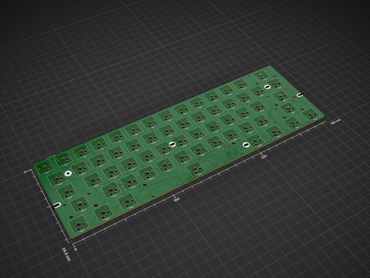
DIY keyboard from scratch for school projects.
Jam1 is an open-source printed circuit board by MRM1790, from the MRM1790/Simple-Keyboard-Project repository on GitHub. It is a 2-layer board of 285 × 94.6 mm with 156 parts on 108 nets, routed with 1,535 tracks and 164 vias.
It is built around the ATMEGA32U4-AU and MIC5219-2.5YM5. Its parts include 67 switches, 63 diodes, 8 capacitors, 7 resistors and 2 ICs. It belongs with the keyboards and input boards and the AVR (ATmega, ATtiny) boards of this library.


DIY keyboard from scratch for school projects. This block diagram displays what parts are considered using in this project. As the following goes, Key switches (Kailh or cherry MX) it is possible to use Choc switches (boxed switches) but for now we are sticking to kailh or cherry mx switches. We are using 3 pin switches for this project. For proof of concept, we have thought about doing a cardboard box with a "WSAD" arrow keys for now. Eventually we will do a full 74 keyboard switches. Microcontroller we plan on using is an Arduino pro micro controller that has a USB C connection for the wire to be connected to the computer or laptop. The goal is to have a keyboard matrix which are key switches that have diodes and wires soldered on each other to create columns and rows to utilize more of the pins that are on the Arduino Pro Microcontroller. Once that is set up then the user should be able to press a input on the proof of concept model and should display either numbers or letters to the output display monitor.
ATTENTION: For the BOM files, designators, and CPL we recommended ordering through JLC PCB since it is configured in their version of excel and ordering process. QMK Toolbox will be needed to upload the code in the circuit board which a link will be provided here https://qmk.fm/toolbox
ATTENTION: THE SOFTWARE FOR THE KEYBOARD IS LABELED AS BOTH "KEYBOARD.JSON" AND "KEYMAP C" AND THE MAIN THING THAT YOU WILL NEED IS THE FILE THAT SAYS "jam61_default.HEX" then you will plug that into the QMK Toolbox application, and press the reset button on the circuit board in order to flash it. Once you hit the reset button in Toolbox hit flash prompt and the Hex file will go into the circuit.
| Qty | Value | Footprint | References |
|---|---|---|---|
| 62 | 1N4148 | Diode_SMD:D_SOD-123 | D1, D2, D10, D11, D12, D13, D14, D15, D16, D17, D18, D19, D20, D21, D22, D23 +46 |
| 4 | Stabilizer | Hotswappable:Stabilizer_MX_2.00u | SW64, SW66, SW68, SW70 |
| 3 | 1uF | Capacitor_SMD:C_0805_2012Metric | C1, C4, C7 |
| 3 | VAL** | hole:PKRH | HOLE, HOLE, HOLE |
| 2 | 10K | Resistor_SMD:R_0805_2012Metric | R5, R7 |
| 2 | 10uF | Capacitor_SMD:C_0805_2012Metric | C5, C6 |
| 2 | 22ohms | Resistor_SMD:R_0805_2012Metric | R3, R4 |
| 2 | 22pF | Capacitor_SMD:C_0805_2012Metric | C2, C3 |
| 2 | 5.1K | Resistor_SMD:R_0805_2012Metric | R1, R2 |
| 2 | Alt | Hotswappable:Hotswap_MX_Plated_1.00u | SW56, SW58 |
| 2 | Ctrl | Hotswappable:Hotswap_MX_Plated_1.00u | SW54, SW61 |
| 2 | VAL** | hole:PKRHSL | HOLE, HOLE |
| 2 | Windows | Hotswappable:Hotswap_MX_Plated_1.00u | SW55, SW60 |
| 1 | '" | Hotswappable:Hotswap_MX_Plated_1.00u | SW40 |
| 1 | -_ | Hotswappable:Hotswap_MX_Plated_1.00u | SW12 |
| 1 | 0) | Hotswappable:Hotswap_MX_Plated_1.00u | SW11 |
| 1 | 0.1uF | Capacitor_SMD:C_0805_2012Metric | C8 |
| 1 | 1! | Hotswappable:Hotswap_MX_Plated_1.00u | SW2 |
| 1 | 16MHZ | Crystal:Crystal_SMD_3225-4Pin_3.2x2.5mm | Y1 |
| 1 | 1Kohms | Resistor_SMD:R_0805_2012Metric | R6 |
| 1 | 2@ | Hotswappable:Hotswap_MX_Plated_1.00u | SW3 |
| 1 | 3# | Hotswappable:Hotswap_MX_Plated_1.00u | SW4 |
| 1 | 4$ | Hotswappable:Hotswap_MX_Plated_1.00u | SW5 |
| 1 | 5% | Hotswappable:Hotswap_MX_Plated_1.00u | SW6 |
| 1 | 500mA | Fuse:Fuse_1206_3216Metric | F1 |
| 1 | 6^ | Hotswappable:Hotswap_MX_Plated_1.00u | SW7 |
| 1 | 7& | Hotswappable:Hotswap_MX_Plated_1.00u | SW8 |
| 1 | 8* | Hotswappable:Hotswap_MX_Plated_1.00u | SW9 |
| 1 | 9( | Hotswappable:Hotswap_MX_Plated_1.00u | SW10 |
| 1 | :; | Hotswappable:Hotswap_MX_Plated_1.00u | SW39 |
| 1 | <. | Hotswappable:Hotswap_MX_Plated_1.00u | SW50 |
| 1 | =+ | Hotswappable:Hotswap_MX_Plated_1.00u | SW13 |
| 1 | >. | Hotswappable:Hotswap_MX_Plated_1.00u | SW51 |
| 1 | ?/ | Hotswappable:Hotswap_MX_Plated_1.00u | SW52 |
| 1 | A | Hotswappable:Hotswap_MX_Plated_1.00u | SW30 |
| 1 | ATmega32U4-A | Package_QFP:TQFP-44_10x10mm_P0.8mm | U1 |
| 1 | B | Hotswappable:Hotswap_MX_Plated_1.00u | SW47 |
| 1 | BS | Hotswappable:Hotswap_MX_Plated_1.00u | SW14 |
| 1 | C | Hotswappable:Hotswap_MX_Plated_1.00u | SW45 |
| 1 | Caps LK | Hotswappable:Hotswap_MX_Plated_1.00u | SW29 |
| 1 | D | Hotswappable:Hotswap_MX_Plated_1.00u | SW32 |
| 1 | E | Hotswappable:Hotswap_MX_Plated_1.00u | SW18 |
| 1 | Enter | Hotswappable:Hotswap_MX_Plated_1.00u | SW41 |
| 1 | Esc/Acc | Hotswappable:Hotswap_MX_Plated_1.00u | SW1 |
| 1 | F | Hotswappable:Hotswap_MX_Plated_1.00u | SW33 |
| 1 | Function | Hotswappable:Hotswap_MX_Plated_1.00u | SW59 |
| 1 | G | Hotswappable:Hotswap_MX_Plated_1.00u | SW34 |
| 1 | H | Hotswappable:Hotswap_MX_Plated_1.00u | SW35 |
| 1 | I | Hotswappable:Hotswap_MX_Plated_1.00u | SW23 |
| 1 | J | Hotswappable:Hotswap_MX_Plated_1.00u | SW36 |
| 1 | K | Hotswappable:Hotswap_MX_Plated_1.00u | SW37 |
| 1 | L | Hotswappable:Hotswap_MX_Plated_1.00u | SW38 |
| 1 | M | Hotswappable:Hotswap_MX_Plated_1.00u | SW49 |
| 1 | MIC5219-2.5YM5 | Package_TO_SOT_SMD:SOT-23-5 | U2 |
| 1 | N | Hotswappable:Hotswap_MX_Plated_1.00u | SW48 |
| 1 | O | Hotswappable:Hotswap_MX_Plated_1.00u | SW24 |
| 1 | P | Hotswappable:Hotswap_MX_Plated_1.00u | SW25 |
| 1 | Q | Hotswappable:Hotswap_MX_Plated_1.00u | SW16 |
| 1 | R | Hotswappable:Hotswap_MX_Plated_1.00u | SW19 |
| 1 | Red | LED_SMD:LED_0201_0603Metric | D63 |
| 1 | Reset Switch | Button_Switch_SMD:SW_SPST_SKQG_WithStem | SW67 |
| 1 | S | Hotswappable:Hotswap_MX_Plated_1.00u | SW31 |
| 1 | Shift | Hotswappable:Hotswap_MX_Plated_1.00u | SW42 |
| 1 | Shift (Right) | Hotswappable:Hotswap_MX_Plated_1.00u | SW53 |
| 1 | Spacebar | Hotswappable:Hotswap_MX_Plated_1.00u | SW57 |
| 1 | Stabilizer | Hotswappable:Stabilizer_MX_6.25u | SW62 |
| 1 | T | Hotswappable:Hotswap_MX_Plated_1.00u | SW20 |
| 1 | Tab | Hotswappable:Hotswap_MX_Plated_1.00u | SW15 |
| 1 | U | Hotswappable:Hotswap_MX_Plated_1.00u | SW22 |
| 1 | USB_C_Receptacle_USB2.0_16P | Connector_USB:USB_C_Receptacle_HRO_TYPE-C-31-M-12 | J2 |
| 1 | V | Hotswappable:Hotswap_MX_Plated_1.00u | SW46 |
| 1 | VAL** | hole:PKRHC | HOLE |
| 1 | W | Hotswappable:Hotswap_MX_Plated_1.00u | SW17 |
| 1 | X | Hotswappable:Hotswap_MX_Plated_1.00u | SW44 |
| 1 | Y | Hotswappable:Hotswap_MX_Plated_1.00u | SW21 |
| 1 | Z | Hotswappable:Hotswap_MX_Plated_1.00u | SW43 |
| 1 | [{ | Hotswappable:Hotswap_MX_Plated_1.00u | SW26 |
| 1 | |\ | Hotswappable:Hotswap_MX_Plated_1.00u | SW28 |
| 1 | }] | Hotswappable:Hotswap_MX_Plated_1.00u | SW27 |


risejohan/2Bit
In this repo we can see some designs with free use for the community, 2 Bit electronic


tominabox1/Le-Chiffre-Keyboard
Great thanks goes to Jake at P3D for really making the case amazing and open sourcing his work. Check him out at P3Dstore.com

The-Royal/The_Royal_Open-Source-Projects
A Master Repository For All things Royal Made

dpapavas/lagrange-keyboard
A configurable, handwired, ergonomic keyboard

dmcke5/ZenDeck
This is the second revision of my Mini PC based handheld Gaming PC! It is designed for a Beelink SER 5 Mini PC but could be adapted to other systems by changing the mounting brackets and outlet plate.
It measures 285 × 94.6 mm and has 2 copper layers, 1.6 mm thick.
156 parts, built around the ATMEGA32U4-AU and MIC5219-2.5YM5. The full list of its parts is on this page, with links to each part's symbol and footprint where PCBKit's library has them.
From the MRM1790/Simple-Keyboard-Project repository on GitHub, at the commit this page was made from: the board is Jam1.kicad_pcb and its schematic Jam1.kicad_sch. PCBKit opens the board in the browser, with nothing to install.
Its repository states no licence, so its author keeps all rights: ask MRM1790 before reusing the design.