4 layers100 × 99.4 mm

 LeoDJ/USB-C_PD_PSU29
A 5-60V bidirectional buck-boost-converter, also capable of 240W USB PD EPR (48V 5A)
USB C PSU is an open-source printed circuit board by LeoDJ, from the LeoDJ/USB-C_PD_PSU repository on GitHub. It is an 8-layer board of 50 × 50 mm with 149 parts on 131 nets, routed with 1,298 tracks and 616 vias.
It is built around the CH32X035G8U6, SIT3088ETK and TPS22915CYFPR, with the AP2112K-3.3, LIS3DH and B110WS among its other parts. Its parts include 43 resistors, 39 capacitors, 11 ICs, 8 connectors and 7 switches. It belongs with the power and interfaces and adapters boards and the RISC-V boards of this library.


[!WARNING] This is a WIP project. It is not yet recommended to reproduce it in its current state.
A bidirectional buck-boost DC-DC converter with the following features:
TI BQ25758A DC-DC controllerWCH CH32X035 as the USB Type-C PD controller (hopefully*)TI TPD4S480)XT30 connectors for power in/outputCH32X035* depending on the yet-to-be-written PD firmware (and an actually functioning DC-DC converter layout :P)
You can follow the Mastodon thread for more up-to-date progress on this project.
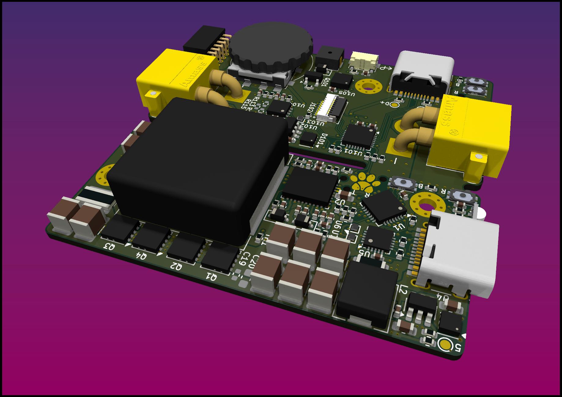
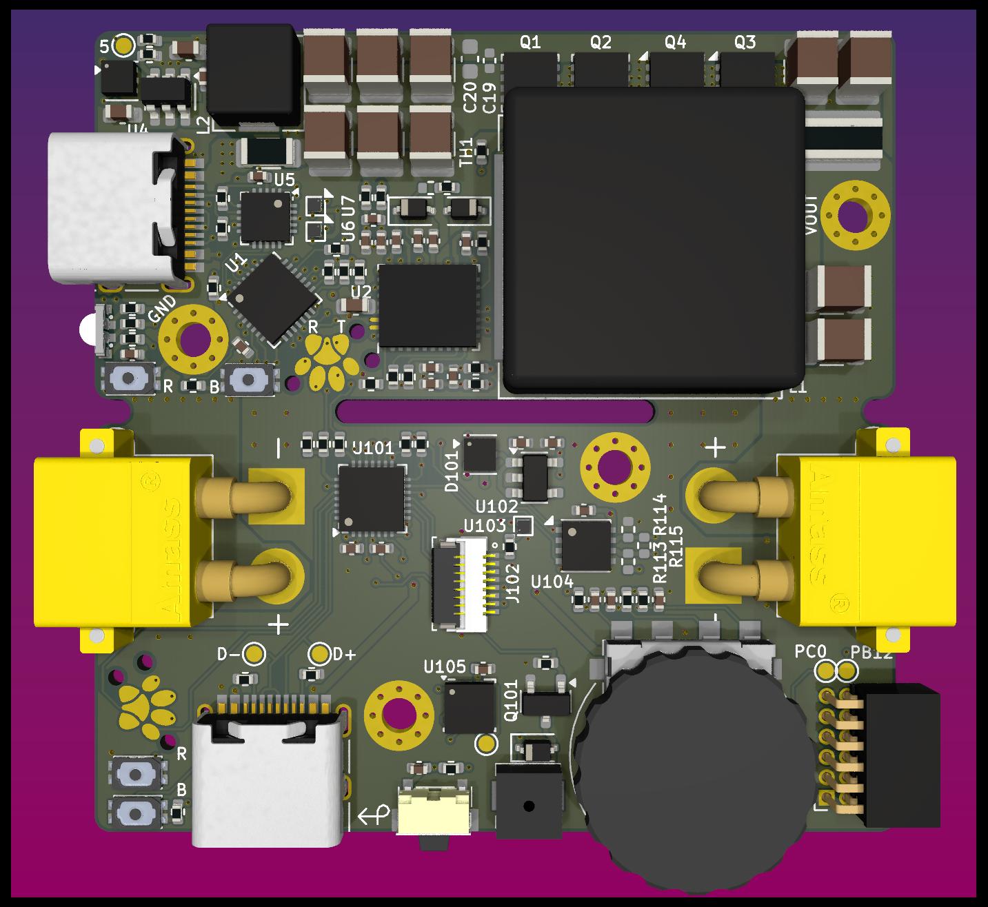
The v1.0 PCB is designed in 8 layers, but 6 would probably suffice too. Thus inner layers 3 and 4 were designed as containing only more GND / power copper pours and can probably be left out, only leading to a reduction of a combined copper thickness from 175µm to 140µm.
1.0mmRemove MarkTop)Yes - 200 x 200mm (saves on shipping cost)| Qty | Value | Footprint | References |
|---|---|---|---|
| 14 | 5k1 | Resistor_SMD:R_0402_1005Metric | R15, R16, R21, R24, R25, R26, R27, R101, R102, R103, R106, R116, R117, R118 |
| 13 | TestPoint | TestPoint:TestPoint_Pad_D1.0mm | TP1, TP2, TP5, TP6, TP7, TP8, TP16, TP17, TP18, TP19, TP20, TP21, TP105 |
| 10 | 10k | Resistor_SMD:R_0402_1005Metric | R14, R28, R31, R104, R107, R109, R110, R111, R112, TH1 |
| 10 | 10u 100V | Capacitor_SMD:C_1210_3225Metric | C18, C21, C22, C23, C24, C25, C26, C29, C30, C31 |
| 9 | 100n | Capacitor_SMD:C_0402_1005Metric | C1, C2, C10, C17, C103, C105, C106, C107, C108 |
| 7 | 0 | Resistor_SMD:R_0402_1005Metric | R17, R19, R20, R22, R23, R29, R30 |
| 6 | 100n 100V | Capacitor_SMD:C_0402_1005Metric | C3, C4, C6, C8, C9, C19 |
| 5 | 10 | Resistor_SMD:R_0402_1005Metric | R2, R3, R4, R6, R105 |
| 4 | 100V 50A | Package_SON:Diodes_PowerDI3333-8 | Q1, Q2, Q3, Q4 |
| 4 | 1u | Capacitor_SMD:C_0402_1005Metric | C32, C104, C109, C110 |
| 3 | 1u 100V | Capacitor_SMD:C_0603_1608Metric | C13, C16, C20 |
| 3 | B110WS | Diode_SMD:D_SOD-323 | D1, D2, D102 |
| 3 | GND | MountingHole:MountingHole_2.2mm_M2_Pad_Via | H2, H101, H102 |
| 3 | TPS22915CYFPR | Package_BGA:Texas_PicoStar_BGA-4_0.758x0.758mm_Layout2x2_P0.4mm | U6, U7, U103 |
| 2 | 1u 25V | Capacitor_SMD:C_0402_1005Metric | C101, C102 |
| 2 | 470n | Capacitor_SMD:C_0402_1005Metric | C5, C7 |
| 2 | 4u7 25V | Capacitor_SMD:C_0402_1005Metric | C14, C15 |
| 2 | 680 | Resistor_SMD:R_0402_1005Metric | R113, R114 |
| 2 | Boot | LCSC:SW-SMD_4P-L3.0-W2.0-P0.85-LS3.5 | SW2, SW104 |
| 2 | CH32X035G8U6 | Package_DFN_QFN:QFN-28-1EP_4x4mm_P0.4mm_EP2.6x2.6mm | U1, U101 |
| 2 | PMEG6010CPA | Package_SON:HUSON-3-1EP_2x2mm_P1.3mm_EP1.1x1.6mm | D5, D101 |
| 2 | Reset | LCSC:SW-SMD_4P-L3.0-W2.0-P0.85-LS3.5 | SW3, SW103 |
| 2 | TC2030 | Paw-Connect:Paw-Connect_RevB_TC2030-IDC-NL_2x03_P1.27mm_Vertical | J3, J103 |
| 2 | USB_C_Receptacle_USB2.0_16P | Connector_USB:USB_C_Receptacle_HRO_TYPE-C-31-M-12 | J1, J101 |
| 1 | clipboard:e777734a-e85c-4367-9ebd-f48524917f5c | ||
| 1 | 120 | Resistor_SMD:R_0402_1005Metric | R115 |
| 1 | 22u 10V | Capacitor_SMD:C_0603_1608Metric | C11 |
| 1 | 22uH <250mOhm | Inductor_SMD:L_Sunlord_MWSA0503S | L2 |
| 1 | 3.3uH 4-5mOhm | Inductor_SMD:L_Chilisin_BMRF00171770 | L1 |
| 1 | 47k | Resistor_SMD:R_0402_1005Metric | R13 |
| 1 | 51k | Resistor_SMD:R_0402_1005Metric | R18 |
| 1 | 5m | Resistor_SMD:R_1020_2550Metric_Pad1.33x5.20mm_HandSolder | R5 |
| 1 | 5m | Resistor_SMD:R_1206_3216Metric | R1 |
| 1 | AO3400A | Package_TO_SOT_SMD:SOT-23 | Q101 |
| 1 | AP2112K-3.3 | Package_TO_SOT_SMD:SOT-23-5 | U102 |
| 1 | BQ25758A | LeoDJ-kicad:Texas_RRV0036A_VQFN-36-1EP_5x6mm_P0.5mm_EP3.6x4.6mm_ThermalVias | U2 |
| 1 | Buzzer | LCSC:BUZ-SMD_L4.0-W4.0-P3.50-L | BZ101 |
| 1 | D+ | TestPoint:TestPoint_Pad_D1.0mm | TP104 |
| 1 | D- | TestPoint:TestPoint_Pad_D1.0mm | TP103 |
| 1 | Expansion | Connector_PinSocket_1.27mm:PinSocket_2x06_P1.27mm_Horizontal | J104 |
| 1 | G*** | kibuzzard-67A54591 | kibuzzard-67A54591 |
| 1 | LED_ABGR | LCSC:LED-ARRAY-SMD_MHS110FRGBCT | D99 |
| 1 | LIS3DH | Package_LGA:LGA-16_3x3mm_P0.5mm_LayoutBorder3x5y | U105 |
| 1 | LMR51610XDBVR | Package_TO_SOT_SMD:SOT-23-6 | U4 |
| 1 | LOGO | LeoDJ-kicad:Logo_PCBDerg_Mask_10mm | G*** |
| 1 | PB12 | TestPoint:TestPoint_Pad_D1.0mm | TP107 |
| 1 | PC0 | TestPoint:TestPoint_Pad_D1.0mm | TP106 |
| 1 | PG | TestPoint:TestPoint_Pad_D1.0mm | TP11 |
| 1 | SIQ-02FVS3 | LeoDJ-kicad:SW-SMD_SIQ-02FVS3_1 | SW101 |
| 1 | SIT3088ETK | Package_DFN_QFN:DFN-8-1EP_3x3mm_P0.65mm_EP1.55x2.4mm | U104 |
| 1 | ST7789 LCD | LCSC:FPC-SMD_8P-P0.50_HCTL_HC-FPC-05-10-8RLTAG | J102 |
| 1 | STAT | TestPoint:TestPoint_Pad_D1.0mm | TP12 |
| 1 | SW_Back | LCSC:SW-SMD_TS24CA | SW102 |
| 1 | SW_Reverse | LCSC:SW-SMD_MSK12CO2 | SW1 |
| 1 | TPD4S480RUKR | Package_DFN_QFN:WQFN-20-1EP_3x3mm_P0.4mm_EP1.7x1.7mm | U5 |
| 1 | VIN | Connector_AMASS:AMASS_XT30PW-M_1x02_P2.50mm_Horizontal | J4 |
| 1 | VOUT | MountingHole:MountingHole_2.2mm_M2_Pad_Via | H1 |
| 1 | VOUT | Connector_AMASS:AMASS_XT30PW-M_1x02_P2.50mm_Horizontal | J2 |
The 148 most common of 149 parts.

LVladymyr/WAFEL-Evaluation-Board
Evaluation board for TI BQ76952 multi-chemistry BMS IC

wszeto9/ESP32-S3-HUB75-Driver
This board serves as the Matrix Display driver for MIT's 2.007 gameboards in Spring 2024 and Spring 2025. The board can take 4 button inputs, Stemma-QT I2C sensors, and breaks out 8 GPIO pins for future use.

jppang/ESP32_MicroPython_LVGL_ST7789
Try to build an ESP32 firmware with LVGL and ST7789 drivers inside.


anhldptit2610/dalws
This project is my attempt to learn about microcontroller and PCB design. Now I realize that making a full, complete electronic project is super hard.

sequoia-hope/rp2350-motor-controller
An RP2350 based brushless motor controller

Kaiser041224/HPM5361-RMCS_Slave-Pro
HPM5361-RMCSSlave-V1.0 是一个基于 KiCad 9 的硬件工程,核心主控为 HPM5361ICB1。从顶层框图、层级原理图和关键器件选型来看,这块板更像一块面向机器人/运动控制场景的从控板,用于通信汇聚、PWM 外设输出、姿态感知、板载存储和基础人机交互。
It measures 50 × 50 mm and has 8 copper layers, 1.01 mm thick.
149 parts, built around the CH32X035G8U6, SIT3088ETK, TPS22915CYFPR and AP2112K-3.3. The full list of its parts is on this page, with links to each part's symbol and footprint where PCBKit's library has them.
From the LeoDJ/USB-C_PD_PSU repository on GitHub, at the commit this page was made from: the board is Hardware/USB-C PSU.kicad_pcb and its schematic Hardware/CC_Protect.kicad_sch. PCBKit opens the board in the browser, with nothing to install.
Its repository states no licence, so its author keeps all rights: ask LeoDJ before reusing the design.