
2 layers142.5 × 106.3 mm
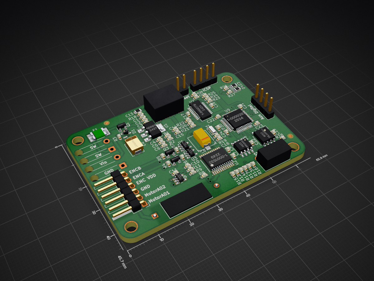
EFM Motor Control PCB
Motor PCB is an open-source printed circuit board by LeemanGeophysicalLLC, from the LeemanGeophysicalLLC/NSSL_EFM_Motor_Control_PCB repository on GitHub, published under the MIT licence. It is a 2-layer board of 65.9 × 45.7 mm with 88 parts on 95 nets, routed with 718 tracks and 86 vias.
Its parts include 30 resistors, 24 capacitors, 9 ICs, 8 connectors and 4 diodes. It belongs with the robots and motor control boards of this library.
One of the paddles on the instrument houses a motor driver, which reads motor speed
from an encoder and controls power to the motor to maintain a constant rotation rate
of the instrument. We also monitor the current supplied to the motor and the
temperature of the control board, logging all of this data to a rolling log file.
This log is used for debugging and diagnosing any flight-related failures.
See the main instrument repo for documentation and the rest of the instrument.
| Qty | Value | Footprint | References |
|---|---|---|---|
| 14 | 1-0000007 | capacitors_0603:1-0000007 | C3, C4, C7, C9, C10, C11, C12, C17, C18, C20, C21, C22, C23, C24 |
| 9 | 1-0000010 | resistors_0603:1-0000010 | R4, R5, R6, R7, R8, R9, R19, R28, R29 |
| 7 | 1-0000006 | resistors_0603:1-0000006 | R14, R15, R16, R17, R22, R25, R30 |
| 4 | 1-0000174 | resistors_0603:1-0000174 | R1, R3, R12, R13 |
| 4 | Imperial4 | mechanical:MountingHole_imperial4 | H1, H2, H3, H4 |
| 3 | 1-0000005 | capacitors_0603:1-0000005 | C1, C6, C19 |
| 3 | 1-0000018 | capacitors_0603:1-0000018 | C2, C5, C16 |
| 2 | 1-0000008 | resistors_0603:1-0000008 | R26, R27 |
| 2 | 1-0000009 | resistors_0603:1-0000009 | R11, R18 |
| 2 | 1-0000012 | resistors_0603:1-0000012 | R20, R21 |
| 2 | 1-0000013 | resistors_0603:1-0000013 | R23, R24 |
| 2 | 1-0000017 | capacitors_0603:1-0000017 | C14, C15 |
| 2 | 1-0000163 | mosfets:1-0000163 | Q2, Q3 |
| 2 | 1-0000456 | others:1-0000456 | U3, U4 |
| 2 | Fiducial_1mm_2mm | mechanical:Fiducial_1mm_Mask2mm | FID1, FID2 |
| 2 | NP_Conn_01x02_Relief | np_connectors:SolderWire_1x02_Relief | J1, J2 |
| 2 | NP_Conn_01x04 | np_connectors:PinHeader_1x04_P2.54mm_Vertical | J6, J8 |
| 1 | 1-0000016 | capacitors_0805:1-0000016 | C13 |
| 1 | 1-0000034 | connectors:1-0000034 | J4 |
| 1 | 1-0000176 | capacitors:1-0000176 | C8 |
| 1 | 1-0000196 | regulators:1-0000196 | U1 |
| 1 | 1-0000207 | microcontrollers:1-0000207 | U9 |
| 1 | 1-0000452 | others:1-0000452 | U5 |
| 1 | 1-0000599 | leds_0805:1-0000599 | D4 |
| 1 | 1-0000601 | leds_0805:1-0000601 | D3 |
| 1 | 1-0000721 | crystals_resonators:1-0000721 | Y1 |
| 1 | 1-0000779 | level_shifting:1-0000779 | U7 |
| 1 | 1-0001156 | connectors:1-0001156 | J7 |
| 1 | 1-0001493 | sensors:1-0001493 | U6 |
| 1 | 1-0001532 | motor_drivers:1-0001532 | U2 |
| 1 | 1-0001537 | diodes:1-0001537 | D2 |
| 1 | 1-0001546 | resistors:1-0001546 | R10 |
| 1 | 1-0001547 | fuses:1-0001547 | F1 |
| 1 | 1-0001670 | mosfets:1-0001670 | Q1 |
| 1 | 1-0001672 | diodes:1-0001672 | D1 |
| 1 | 1-0001755 | eeproms:1-0001755 | U8 |
| 1 | 1-0001756 | resistors_0603:1-0001756 | R2 |
| 1 | LOGO | pcb_graphics:PCB Logo Standard | G*** |
| 1 | NP_Conn_01x02 | np_connectors:PinHeader_1x02_P2.54mm_Vertical | J5 |
| 1 | NP_Conn_01x06 | Connector_PinHeader_2.54mm:PinHeader_1x06_P2.54mm_Horizontal | J3 |
| 1 | barepcb | misc:barepcb | PCB1 |

c0pperdragon/C64-Video-Enhancement
Component video modification for the C64 8-bit computer


henrikssn/TurboCAN
This is the official repository for the TurboCAN controller board, designed specifically for the Voron AfterBurner toolhead but can also be used on similar toolheads using NEMA17 steppers.

It measures 65.9 × 45.7 mm and has 2 copper layers, 2.45 mm thick.
88 parts. The full list of its parts is on this page, with links to each part's symbol and footprint where PCBKit's library has them.
From the LeemanGeophysicalLLC/NSSL_EFM_Motor_Control_PCB repository on GitHub, at the commit this page was made from: the board is KiCAD_Project/Motor_PCB.kicad_pcb and its schematic KiCAD_Project/Motor_PCB.kicad_sch. PCBKit opens the board in the browser, with nothing to install.
Its repository publishes it under the MIT licence: you may reuse it on that licence's terms (keep the author's notice, and for a copyleft licence share your changes alike).