2 layers146.1 × 114.3 mm

 KonradWohlfahrt/BirdhouseCameraSystemCameraNode1
ESP32-based camera node project files for the Birdhouse Camera System.
Birdhouse Camera System is an open-source printed circuit board by KonradWohlfahrt, from the KonradWohlfahrt/BirdhouseCameraSystemCameraNode repository on GitHub, published under the CC-BY-4.0 licence. It is a 2-layer board of 70 × 50 mm with 39 parts on 27 nets, routed with 120 tracks and 2 vias.
It is built around the AM312, DS18B20 and PN2222A. Its parts include 8 resistors, 7 connectors, 5 diodes, 3 capacitors and 3 ICs. It belongs with the ESP32 boards of this library.


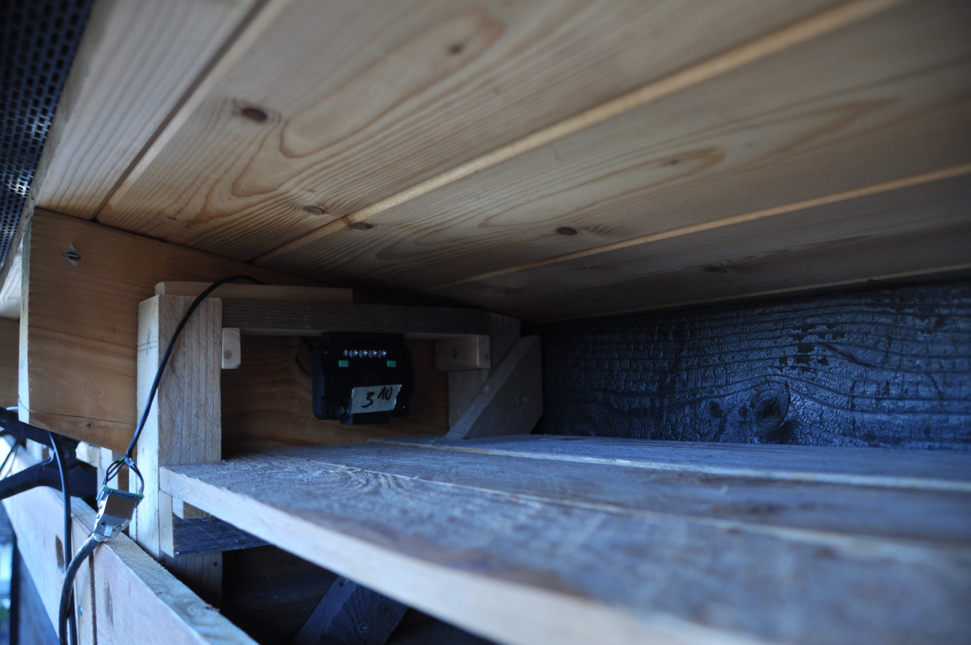
Overview:
This repository contains the firmware, PCB design files, and 3D models for the ESP32-based camera nodes used in the Birdhouse Camera System. The goal of this project is to create a low-cost, modular, and reliable solution for observing bird activity inside multiple birdhouses. Each camera node is built around the ESP32-CAM module. A key focus of this design is reliability and scalability. Instead of relying on WiFi, which can be unstable over longer distances or across multiple installations, the nodes use a wired Ethernet connection via the W5500 Lite module. The hardware has been intentionally designed with accessibility in mind, using mostly through-hole components to make assembly easier for beginners and hobbyists.
Special thanks to NextPCB for supplying me with the printed circuit boards for this project! They offer great production services for your electronic needs! More on that in the blog:
Server Repository
Instructables Guide
Key Features:
Repository Contents:
/cad - 3D printable enclosure models/img - Images of the system/pcb – KiCad project and Gerber files/src – Arduino sketch for the ESP32-CAM| Component | Amount | Silkscreen label |
|---|---|---|
| 1uF | 2 | C1,C2 |
| 100nF | 1 | C3 |
| 5mm IR LED | 5 | D1-D5 |
| JST-XH vertical 4-pin socket | 2 | J3,J5 |
| JST-XH vertical 2-pin socket | 2 | J4,J6 |
| JST-XH vertical 3-pin socket (optional) | 1 | J7 |
| 2N2222A transistor | 1 | Q1 |
| 20k | 1 | R1 |
| 4.7k | 1 | R2 |
| 100r | 5 | R3-R7 |
| 1k | 1 | R8 |
| DIP Switch (optional) | 2 | SW1,SW2 |
| ESP32-CAM (OV3660 recommended) | 1 | U1 |
| AM312 | 1 | U2 |
| DS18B20 (optional) | 1 | U3 |
| W5500 Lite | 1 | - |
| Cables | a few | - |
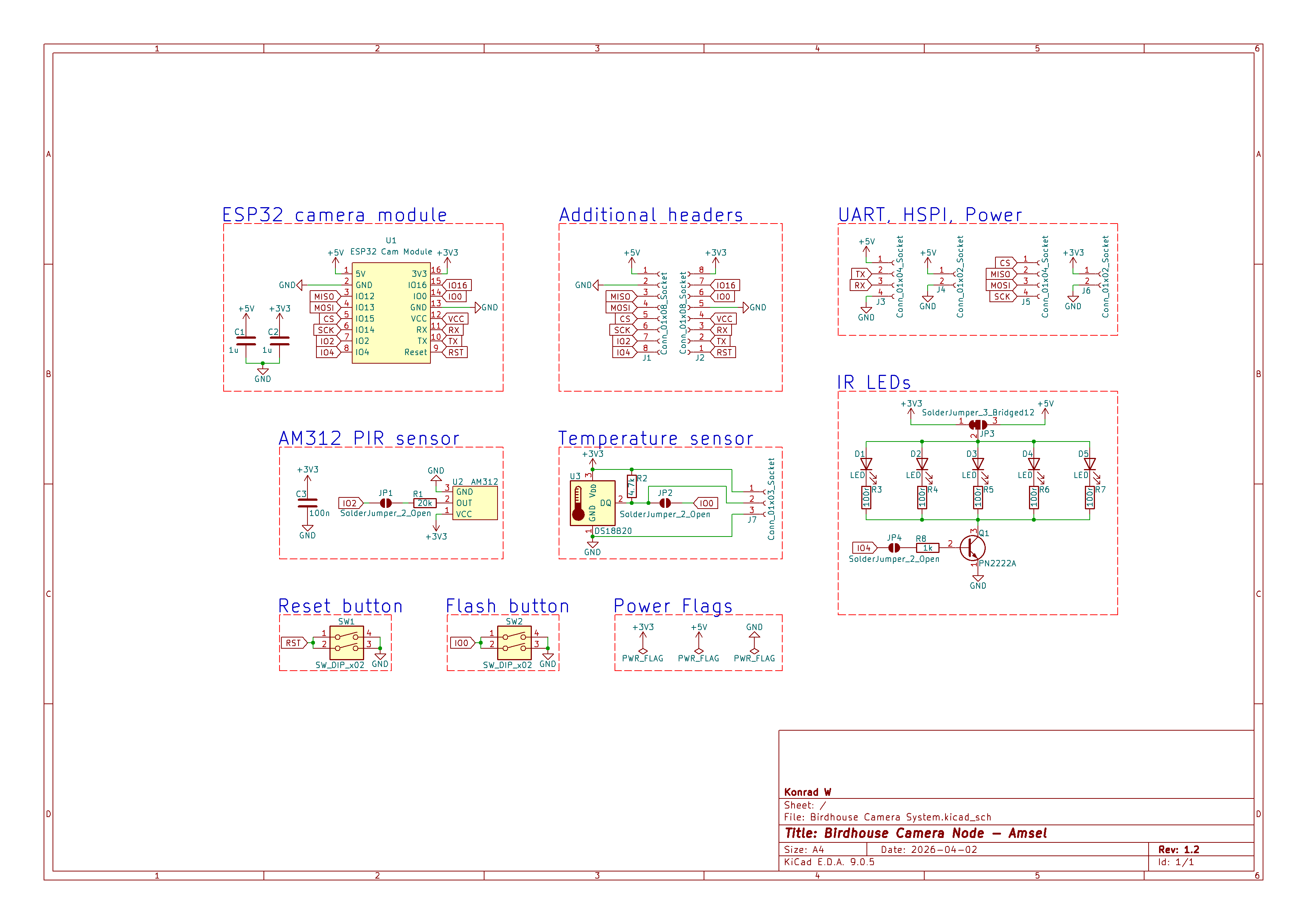
Schematic of the Amsel Camera Node
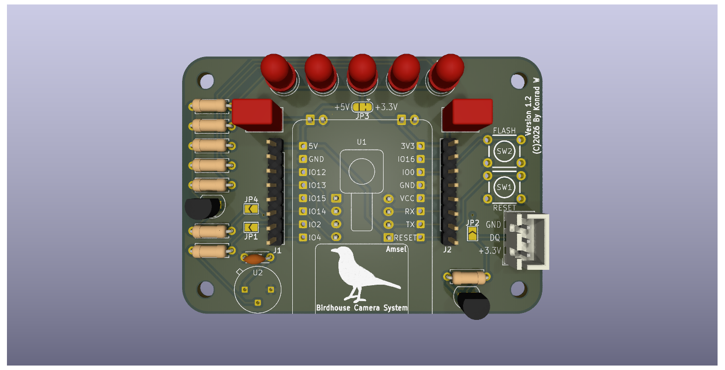
 PCB Render of the Front
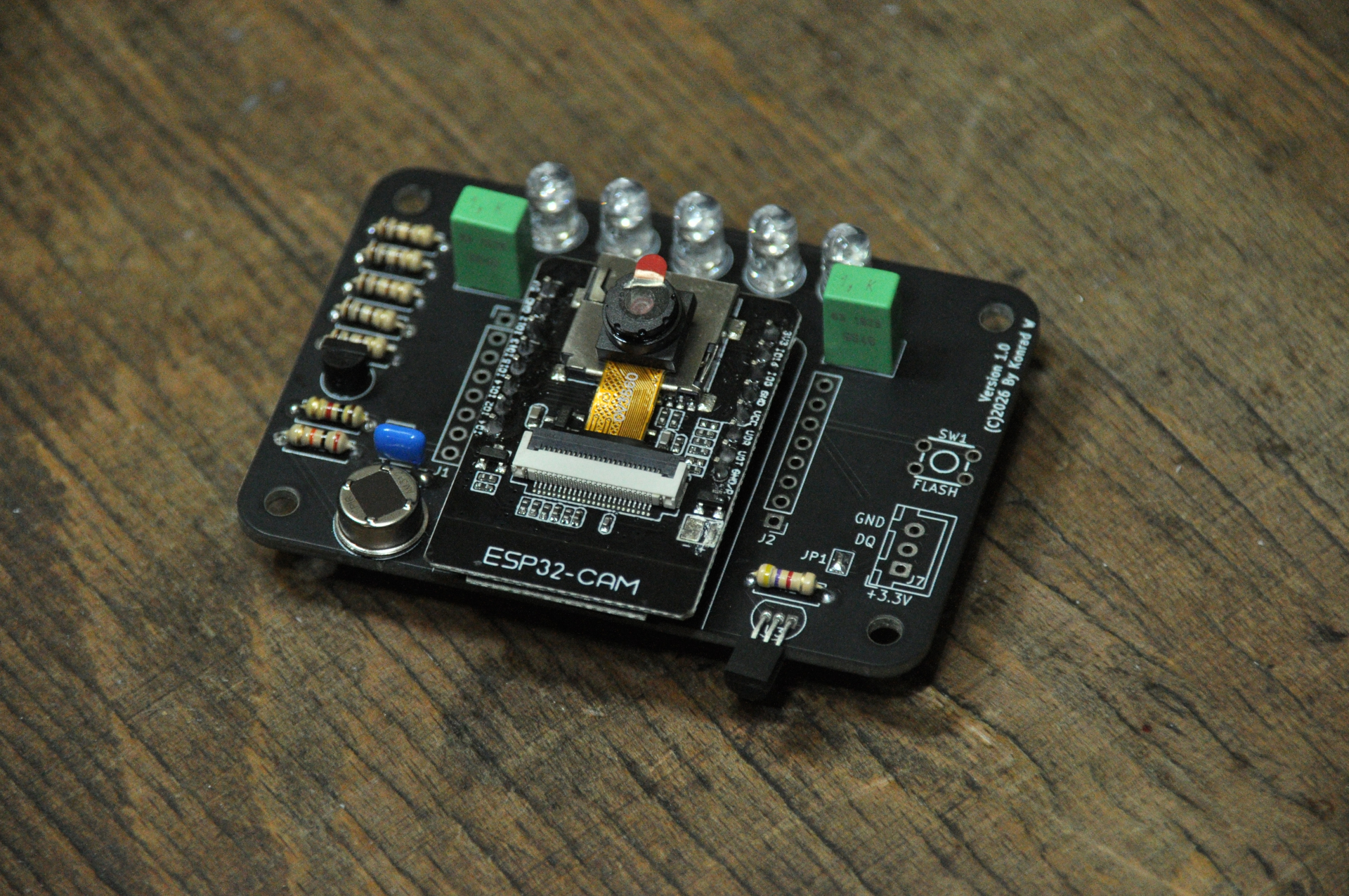
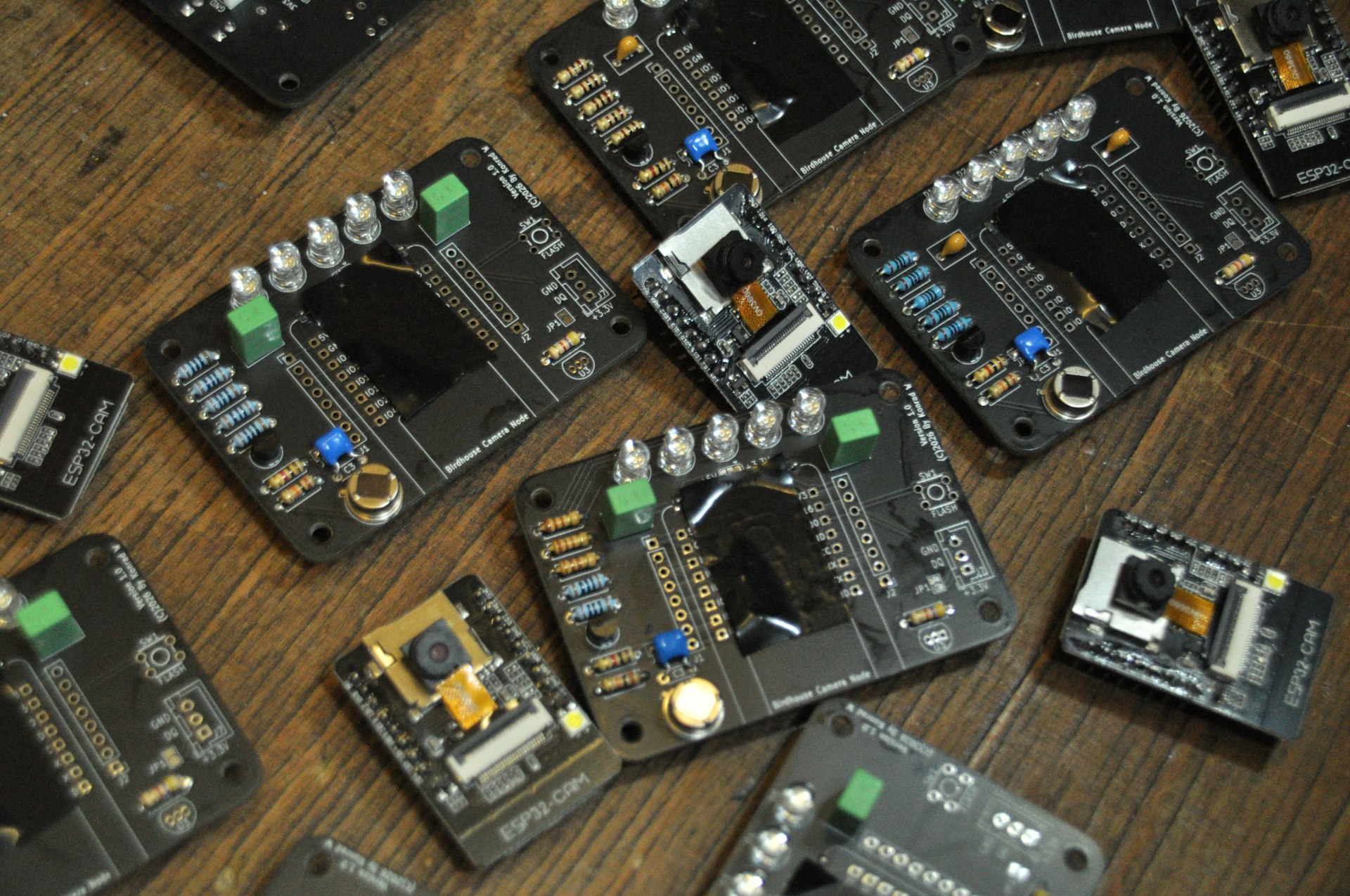
 Finished Camera Node PCB
Programmed with the ArduinoIDE and ESP32 board manager. Install the following libraries:
Uploading:
Board: AI Thinker ESP32-CAM
Settings:
CPU Frequency: "240MHz (WiFi/BT)"
Core Debug Level: "None"
Erase All Flash Before Sketch Upload: "Disabled"
Flash Frequency: "80MHz"
Flash Mode: "QIO"
Partition Scheme: "Minimal SPIFFS (1.9MB APP with OTA/128KB SPIFFS)"

Programmer: "Esptool"
Flashing via the ESP32-CAM programming board. Press the flash button when powering up the device.
OTA:
A new firmware can be flashed using the web page by uploading the correct .bin file or by using the following command:
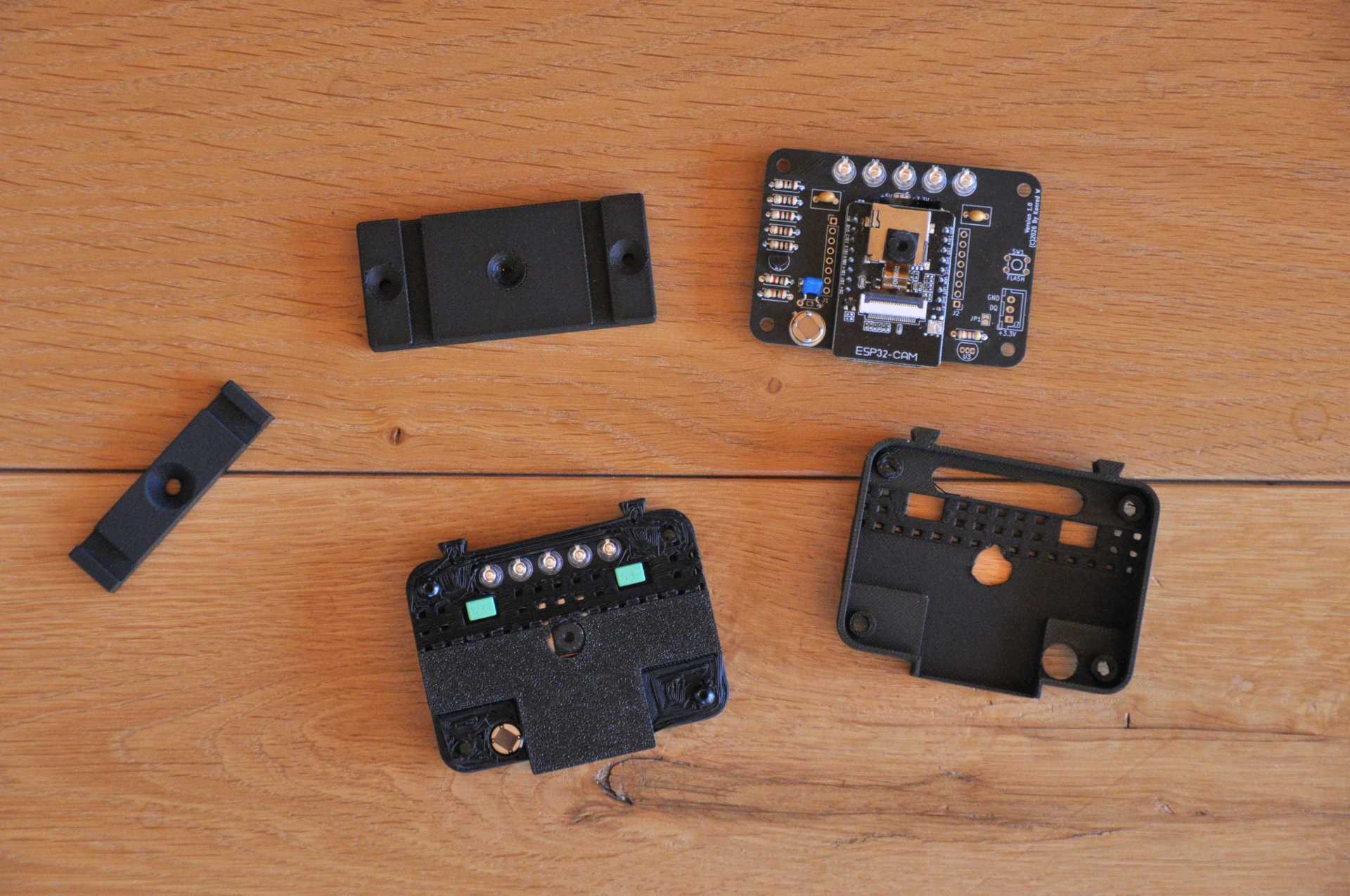
curl -F "update=@<file name>.bin" "http://<esp ip>/update"3D Printed Housing
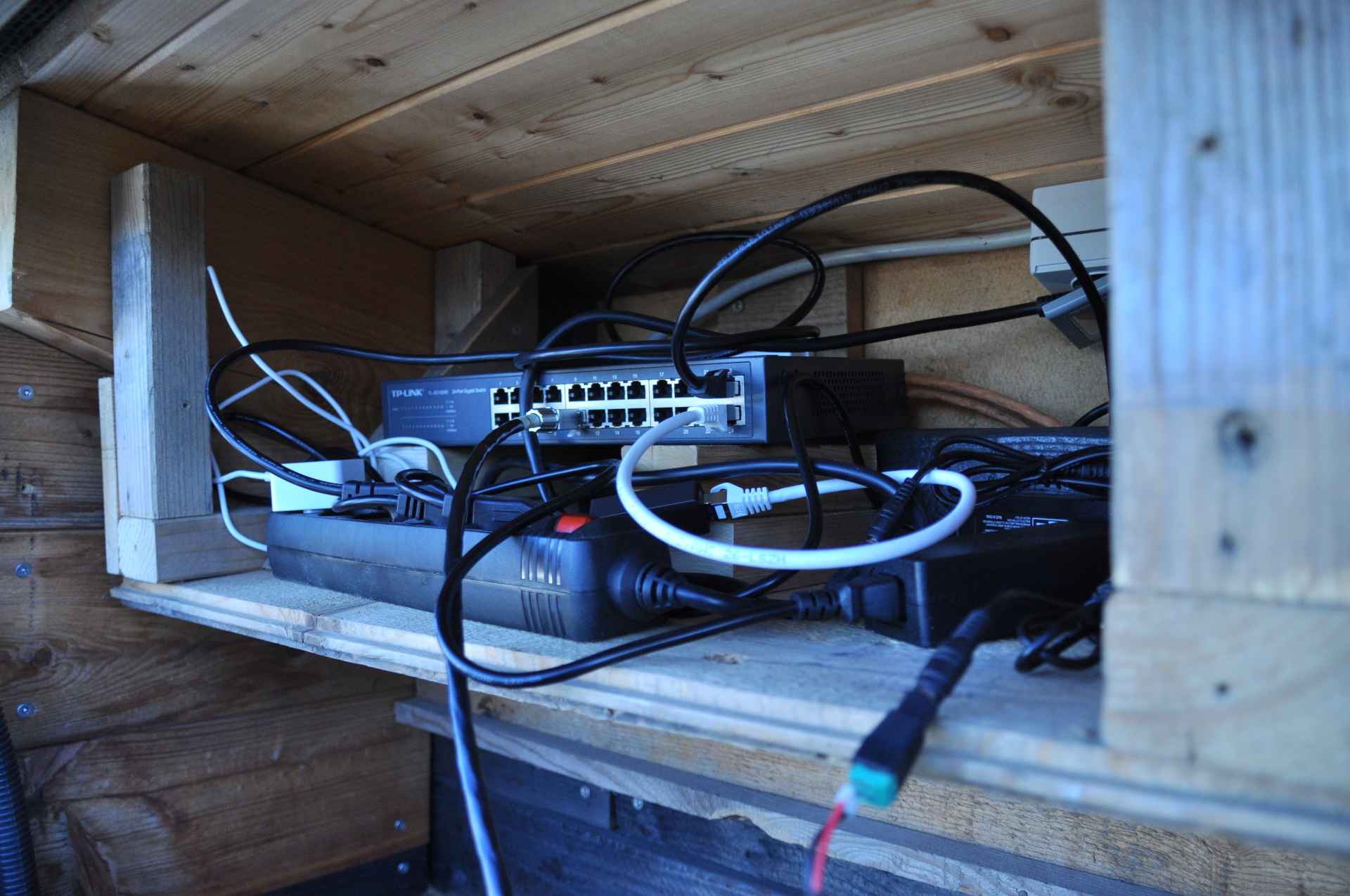
 Installed Camera Node
The beginner friendly PCB is intended to be an easy start for everyone into bird observation. In the future I am planning to add smaller more complex designs that can be used in space-restricted areas. As well as adding crucial changes to the system like Power-over-Ethernet (PoE) and various environmental sensors. The system is open to customizations. I am looking forward to your ideas and improvements!
| Qty | Value | Footprint | References |
|---|---|---|---|
| 5 | 100r | Resistor_THT:R_Axial_DIN0207_L6.3mm_D2.5mm_P7.62mm_Horizontal | R3, R4, R5, R6, R7 |
| 5 | LED | LED_THT:LED_D5.0mm | D1, D2, D3, D4, D5 |
| 3 | SolderJumper_2_Open | Jumper:SolderJumper-2_P1.3mm_Open_TrianglePad1.0x1.5mm | JP1, JP2, JP4 |
| 2 | 1u | Capacitor_THT:C_Rect_L7.0mm_W4.5mm_P5.00mm | C1, C2 |
| 2 | Conn_01x02_Socket | Connector_JST:JST_XH_B2B-XH-A_1x02_P2.50mm_Vertical | J4, J6 |
| 2 | Conn_01x04_Socket | Connector_JST:JST_XH_B4B-XH-A_1x04_P2.50mm_Vertical | J3, J5 |
| 2 | Conn_01x08_Socket | Connector_PinHeader_2.54mm:PinHeader_1x08_P2.54mm_Vertical | J1, J2 |
| 2 | LOGO | LOGO | G***, G*** |
| 2 | SW_DIP_x02 | KonradsLibrary:Tactile Switch 6x6x4.3mm | SW1, SW2 |
| 1 | 100n | Capacitor_THT:C_Disc_D4.3mm_W1.9mm_P5.00mm | C3 |
| 1 | 1k | Resistor_THT:R_Axial_DIN0207_L6.3mm_D2.5mm_P7.62mm_Horizontal | R8 |
| 1 | 20k | Resistor_THT:R_Axial_DIN0207_L6.3mm_D2.5mm_P7.62mm_Horizontal | R1 |
| 1 | 4.7k | Resistor_THT:R_Axial_DIN0207_L6.3mm_D2.5mm_P7.62mm_Horizontal | R2 |
| 1 | AM312 | KonradsLibrary:AM312 | U2 |
| 1 | Conn_01x03_Socket | Connector_JST:JST_XH_B3B-XH-A_1x03_P2.50mm_Vertical | J7 |
| 1 | DS18B20 | Package_TO_SOT_THT:TO-92_Inline | U3 |
| 1 | ESP32 Cam Module | KonradsLibrary:ESP32 Cam Module | U1 |
| 1 | PN2222A | Package_TO_SOT_THT:TO-92_Inline | Q1 |
| 1 | SolderJumper_3_Bridged12 | Jumper:SolderJumper-3_P1.3mm_Bridged12_RoundedPad1.0x1.5mm | JP3 |
The 35 most common of 39 parts.

laemo10/SuperNicePCB
An integrated, multi-sensor UWB anchor PCB designed for real-time indoor object tracking (via Double-Sided Two-Way Ranging) and non-invasive human presence/occupancy monitoring.

nate922/ceilingpuck_v4
Ceiling Puck v4 - smart ceiling sensor/actuator

SolderedElectronics/PIR-Movement-sensor-board-hardware-design
Hardware design, BOM, gerbers and 3D files for PIR-Movement-sensor-board designed by Soldered Electronics.

SolderedElectronics/PIR-movement-sensor-board-qwiic-hardware-design
Hardware design, BOM, gerbers and 3D files for PIR-movement-sensor-board-qwiic designed by Soldered Electronics.

SolderedElectronics/PIR-movement-sensor-board-with-easyC-hardware-design
Hardware design, BOM, gerbers and 3D files for PIR-movement-sensor-board-with-easyC designed by Soldered Electronics.

ThunderSloth/walkin-pir-interface
Battery-Powered PIR Motion Interface (Isolated Dry Contact)

donaldbell/productspeedrun
Let's see how quickly we can get a product idea off the ground.
It measures 70 × 50 mm and has 2 copper layers, 1.6 mm thick.
39 parts, built around the AM312, DS18B20 and PN2222A. The full list of its parts is on this page, with links to each part's symbol and footprint where PCBKit's library has them.
From the KonradWohlfahrt/BirdhouseCameraSystemCameraNode repository on GitHub, at the commit this page was made from: the board is pcb/Birdhouse Camera System.kicad_pcb and its schematic pcb/Birdhouse Camera System.kicad_sch. PCBKit opens the board in the browser, with nothing to install.
Its repository publishes it under the CC-BY-4.0 licence: you may reuse it on that licence's terms (keep the author's notice, and for a copyleft licence share your changes alike).