Skip to the content
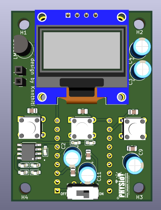
2 layers41.1 × 55.2 mmTemperature sensor, the printed circuit board in 3D

โปรเจกต์นี้เป็นการออกแบบและสร้างวงจรปรับแต่งสัญญาณ (Signal Conditioning) เพื่อแปลงแรงดันจากเซนเซอร์ LM35 ให้เหมาะสมกับ ADC ของ Microcontroller โดยค่าที่ได้จากการทดลองอยู่ในช่วงประมาณ 0.218V – 0.507V และแปลงเป็นค่า ADC…

Size
41.1 × 55.2 mm
Copper layers
2
Thickness
1.6 mm
Parts
41
Nets
33
Pads
110
Tracks, vias
191, 15
Pours
1
Routed
Yes
KiCad
KiCad 8.0 (file 20240108)
Created
6 Feb 2026
Updated
5 Jun 2026

Overview

Temperature sensor is an open-source printed circuit board by Knnthiti, from the Knnthiti/LM35DZ_Temperature_sensor repository on GitHub. It is a 2-layer board of 41.1 × 55.2 mm with 41 parts on 33 nets, routed with 191 tracks and 15 vias.

It is built around the TC7660M/TR, JS202011CQN and TP4056. Its parts include 11 capacitors, 7 resistors, 3 switches and 2 diodes. It belongs with the sensors and measurement boards and the ESP32 boards of this library.

Main components

3

README

README.md

Zero and Span Adjustment Circuit for LM35 Temperature Sensor

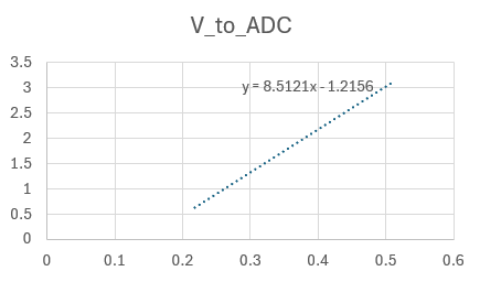
โปรเจกต์นี้เป็นการออกแบบและสร้างวงจรปรับแต่งสัญญาณ (Signal Conditioning) เพื่อแปลงแรงดันจากเซนเซอร์ LM35 ให้เหมาะสมกับ ADC ของ Microcontroller โดยค่าที่ได้จากการทดลองอยู่ในช่วงประมาณ 0.218V – 0.507V และแปลงเป็นค่า ADC ได้ประมาณ 0.64 – 3.10

📐 รายละเอียดการคำนวณ (Calculation)

ข้อมูลในหัวข้อนี้อ้างอิงจาก ผลการทดลองจริง โดยสามารถดูแหล่งข้อมูลได้จากไฟล์ กราฟการทดลอง.xlsx

1. วิเคราะห์สัญญาณขาเข้า (Input Analysis)

ค่าที่วัดได้จากการทดลองจริงมีดังนี้:

อุณหภูมิ (°C)แรงดัน (V)ADC
500.5073.10
450.4542.82
400.4032.35
350.3551.94
300.3121.51
250.2531.00
200.2180.64

2. สมการเส้นตรง (Transfer Function)

ใช้รูปแบบสมการเส้นตรงแบบเดิมคือ $$y = mx + c$$

โดย

  • $m$ คือความชัน (Slope)
  • $c$ คือจุดตัดแกน $y$ (Offset)

2.1 การหาสมการ V_to_ADC

กำหนดให้ $x = V$ และ $y = ADC$

  • แทนค่าจากข้อมูลจริงในไฟล์ กราฟการทดลอง.xlsx (ใช้จุดปลายช่วงวัด)

    • จุดที่ 1: $(V, ADC) = (0.218, 0.64)$
    • จุดที่ 2: $(V, ADC) = (0.507, 3.10)$
  • หาค่าความชัน (Slope) แบบเดิม: $$m = \frac{\Delta ADC}{\Delta V} = \frac{3.10 - 0.64}{0.507 - 0.218} = \frac{2.46}{0.289} = 8.5121$$

  • หาค่าออฟเซต (Intercept): แทนค่าใน $y = mx + c$ ด้วยจุด $(0.218, 0.64)$ $$0.64 = (8.5121 \times 0.218) + c$$ $$0.64 = 1.8556 + c$$ $$c = 0.64 - 1.8556 = -1.2156$$

  • ตรวจสอบกับเส้นแนวโน้ม (Linear Trendline) จะได้ค่าเดียวกันคือ $$m = 8.5121,; c = -1.2156$$

ดังนั้นสมการคือ $$ADC = 8.5121V - 1.2156$$

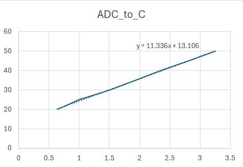
2.2 การหาสมการ ADC_to_C

กำหนดให้ $x = ADC$ และ $y = C$

  • จากการทำเส้นแนวโน้ม (Linear Trendline) ในไฟล์ กราฟการทดลอง.xlsx ได้ค่า $$m = 11.336,; c = 13.106$$

ดังนั้นสมการคือ $$C = 11.336(ADC) + 13.106$$

สรุปสมการจากข้อมูลทดลองจริง (พร้อมกราฟ):

  1. V_to_ADC $$ADC = 8.5121V - 1.2156$$

    กราฟ V_to_ADC จากการทดลองจริง

  2. ADC_to_C $$C = 11.336(ADC) + 13.106$$

    กราฟ ADC_to_C จากการทดลองจริง

จากภาพด้านบน ค่าที่ใช้ใน README เป็นค่าจริงจากการทดลอง และสามารถตรวจสอบรายละเอียดได้จากไฟล์ กราฟการทดลอง.xlsx


🛠 โครงสร้างและการทำงานของวงจร

วงจรนี้ใช้ Op-Amp LM358 ในการจัดการสัญญาณ แบ่งออกเป็นส่วนต่างๆ ดังนี้:

  • Sensor Input: รับสัญญาณจาก LM35-LP ที่ไฟเลี้ยง 3.3V
  • Input Buffer (U2A): ทำหน้าที่เป็น Voltage Follower เพื่อแยกโหลดออกจากตัวเซนเซอร์
  • Zero Adjustment (U3A): ใช้ Potentiometer (RV1) เพื่อปรับแรงดันอ้างอิง (Reference Voltage) สำหรับชดเชยค่า Offset
  • Span Adjustment (U3B): ปรับอัตราขยาย (Gain) เพื่อให้ได้ช่วงแรงดันที่ต้องการ (Span)
  • Output: สัญญาณ $V_{out}$ จะถูกส่งออกทาง Connector J1
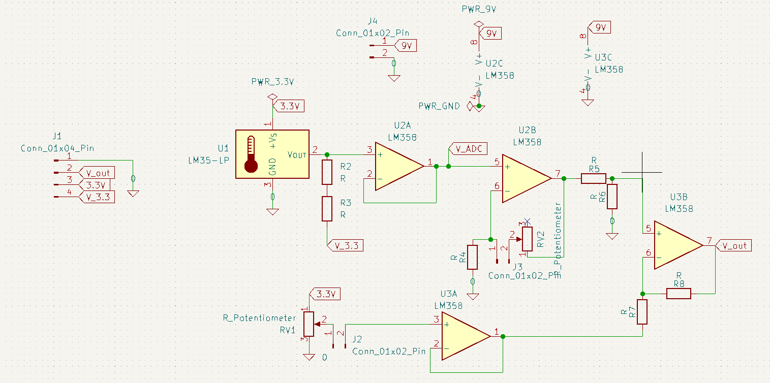
Operational amplifier differential amplifier circuit diagram

📊 ระบบแสดงข้อมูล (Display System)

3D model overview

ระบบแสดงผลถูกแบ่งเป็น 3 โหมดตามปุ่มควบคุม ดังนี้:

  • ปุ่มซ้าย: เข้าโหมด WiFi Manager และเมื่อเชื่อมต่อเครือข่ายสำเร็จ ระบบจะแสดง IP Address สำหรับเชื่อมต่อผ่าน WebSocket
  • ปุ่มกลาง: แสดงค่า อุณหภูมิ ที่วัดได้จากเซนเซอร์
  • ปุ่มขวา: แสดงค่า แรงดันไฟฟ้า ของสัญญาณที่วัดได้
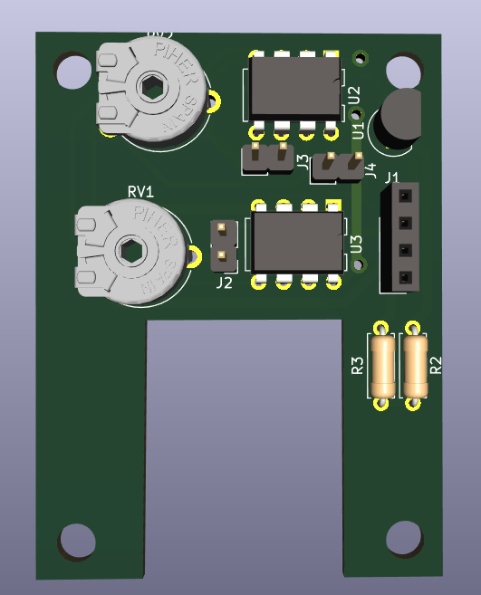
3D model overview

เป็น Zero and span adjustment circuit :

  • R ตัวบน: เป็น Rf ปรับกำลังขยาย
  • R ตัวล่าง: เป็น span ปรับแรงดัน

โค้ดโปรแกรมสามารถดูได้ที่ไฟล์ T_sensor_V3/T_sensor_V3.ino


Parts

41
QtyValueFootprintReferences
60.1uCCapacitor_SMD:C_0805_2012MetricC1, C5, C6, C7, C8, C10
51kLED_SMD:LED_0603_1608Metric_Pad1.05x0.95mm_HandSolderR1, R2, R3, R6, R7
4MountingHoleMountingHole:MountingHole_3.2mm_M3H1, H2, H3, H4
322uCCapacitor_THT:CP_Radial_D5.0mm_P2.00mmC2, C9, C11
3SW_PushSW_Push:SW_TH_Tactile_Omron_B3F-10xxSW1, SW2, SW3
210uCCapacitor_THT:CP_Radial_D5.0mm_P2.00mmC3, C4
120kResistor_THT:R_Axial_DIN0207_L6.3mm_D2.5mm_P10.16mm_HorizontalR5
147kResistor_THT:R_Axial_DIN0207_L6.3mm_D2.5mm_P10.16mm_HorizontalR4
1BAT_3.7VConnector_PinSocket_2.00mm:PinSocket_1x01_P2.00mm_Vertical+
1BAT_GNDConnector_PinSocket_2.00mm:PinSocket_1x01_P2.00mm_Vertical-
1DM-OLED096-636OLED:MODULE_DM-OLED096-636OLED
1ESP32-S3-ZEROesp32s3Zero:MODULE_ESP32-S3-ZEROesp32s3zero
1JS202011CQNJS202011CQN:JS202011CQNOFF ON
1LED_GreenLED_SMD:LED_0603_1608Metric_Pad1.05x0.95mm_HandSolderD1
1LED_RedLED_SMD:LED_0603_1608Metric_Pad1.05x0.95mm_HandSolderD2
1LM35-LPPackage_TO_SOT_THT:TO-92LM35DZ
1LOGOlogo:ROBOTG***
1LOGOlogo:physic_iote_A95_50G***
1LOGOlogo:IERLG***
1LOGOlogo:ioteG***
1LOGOlogo:ichika_137_200G***
1LOGOlogo:KMITLG***
1TC7660TC7660:TC7660TC7660
1TP4056TP4056:SOP127P600X175-9NTP4056

More from Knnthiti/LM35DZ_Temperature_sensor

1
  • 2 layers41.1 × 55.2 mmPCB Temperature sensor V2, the printed circuit board in 3D

    PCB Temperature sensor V2

    Knnthiti/LM35DZ_Temperature_sensor

    โปรเจกต์นี้เป็นการออกแบบและสร้างวงจรปรับแต่งสัญญาณ (Signal Conditioning) เพื่อแปลงแรงดันจากเซนเซอร์ LM35 ให้เหมาะสมกับ ADC ของ Microcontroller โดยค่าที่ได้จากการทดลองอยู่ในช่วงประมาณ 0.218V – 0.507V และแปลงเป็นค่า ADC…

    16 parts

Similar boards

  • 2 layers100 × 90 mmMcu board, the printed circuit board in 3D

    Mcu board

    Kononenko-K/IN12-STM32-Nixie-Clock

    STM32 Nixie clock project.

    66 parts3
  • 4 layers80 × 72 mmPH ORP Card, the printed circuit board in 3D

    PH ORP Card

    brandtks/AquaPicModules

    AquaPic modules, board design and firmware

    118 parts2
  • 2 layersSensor water, the printed circuit board in 3D

    Sensor water

    boiduykhanh/kicad-sensor-water

    73 parts1
  • 4 layers35.6 × 22.9 mmActive Notch Filter Cigar Box Electric Guitar, the printed circuit board in 3D

    Active Notch Filter Cigar Box Electric Guitar

    ardaanbhatia7/Active-Notch-Filter-Cigar-Box-Electric-Guitar

    A complete analog hardware project that designs, simulates, and demonstrates an active notch filter for removing unwanted frequency content in a cigar box electric guitar signal path.

    24 parts
  • 2 layers71.9 × 100 mmVco, the printed circuit board in 3D

    Vco

    cookiemonsternz/Eurorack-VCO

    Also, a lot of eurorack modules are quite bland in terms of design, often lacking any personality and focusing purely on cramming as many knobs in as possible.

    115 parts
  • 2 layers67.6 × 63.8 mmOutAna, the printed circuit board in 3D

    OutAna

    radioelf/OpenPlc

    Hardware for OpenPLC with raspberry PI Z and Mod. software OpenPlc

    92 parts7

Questions

How big is the Temperature sensor PCB?

It measures 41.1 × 55.2 mm and has 2 copper layers, 1.6 mm thick.

What parts does the Temperature sensor use?

41 parts, built around the TC7660M/TR, JS202011CQN and TP4056. The full list of its parts is on this page, with links to each part's symbol and footprint where PCBKit's library has them.

Where can I download the Temperature sensor KiCad files?

From the Knnthiti/LM35DZ_Temperature_sensor repository on GitHub, at the commit this page was made from: the board is PCB_Temperature_sensor_V1/Temperature_sensor.kicad_pcb and its schematic PCB_Temperature_sensor_V1/Temperature_sensor.kicad_sch. PCBKit opens the board in the browser, with nothing to install.

Can I use the Temperature sensor design in my own project?

Its repository states no licence, so its author keeps all rights: ask Knnthiti before reusing the design.