2 layers51.9 × 25.9 mm
 KapiCola/ble-audio-platform
Platforma eksperymentalna BLE Audio oparta na nRF5340 – sprzęt, firmware i testy.
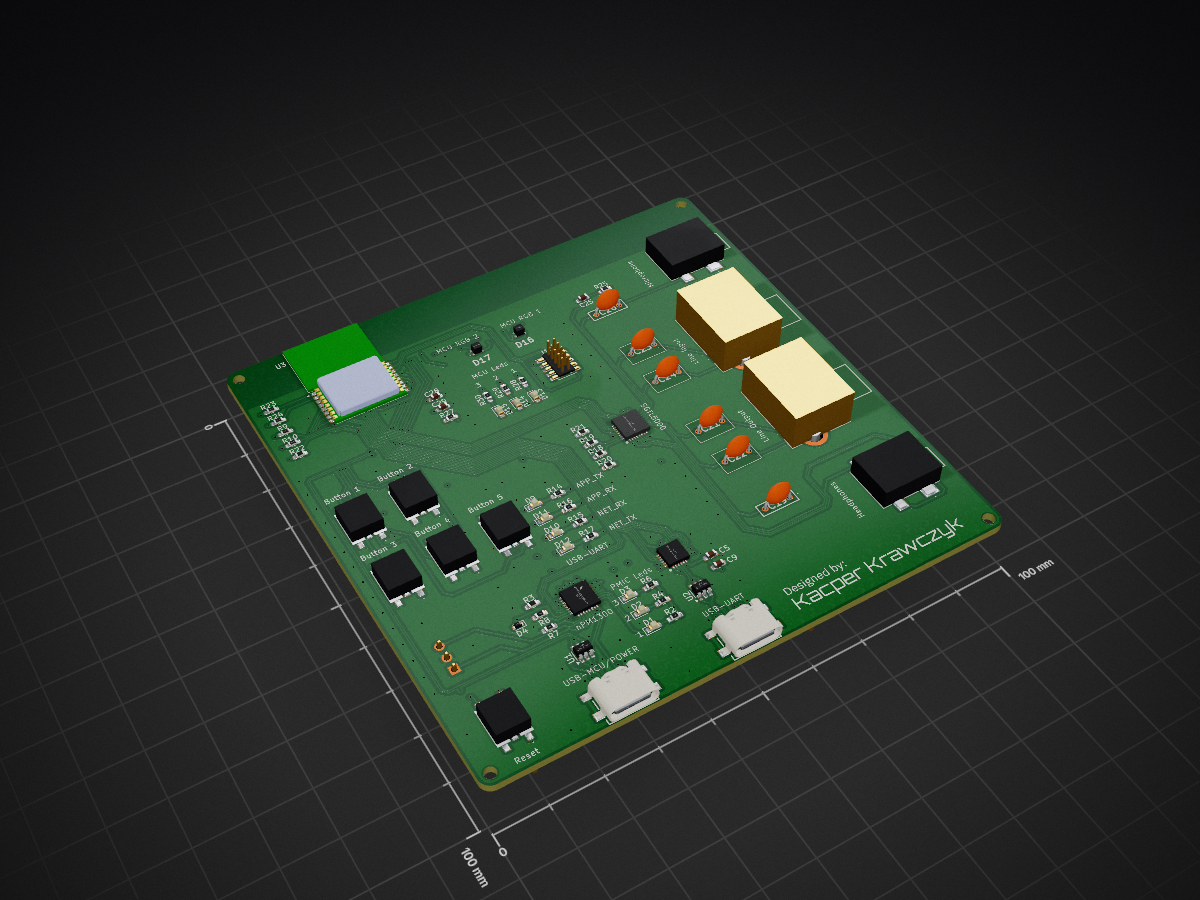
BT40F audio board is an open-source printed circuit board by KapiCola, from the KapiCola/ble-audio-platform repository on GitHub, published under the MIT licence. It is a 4-layer board of 100 × 100 mm with 114 parts on 161 nets, routed with 1,940 tracks and 320 vias.
It is built around the CP2105-F01-GM, SGTL5000XNBA3R2 and USBLC6-2SC6, with the NPM1300-QEAA-R7 among its other parts. Its parts include 36 resistors, 30 capacitors, 17 diodes, 13 connectors and 6 ICs. It belongs with the audio and music and radio and wireless boards of this library.


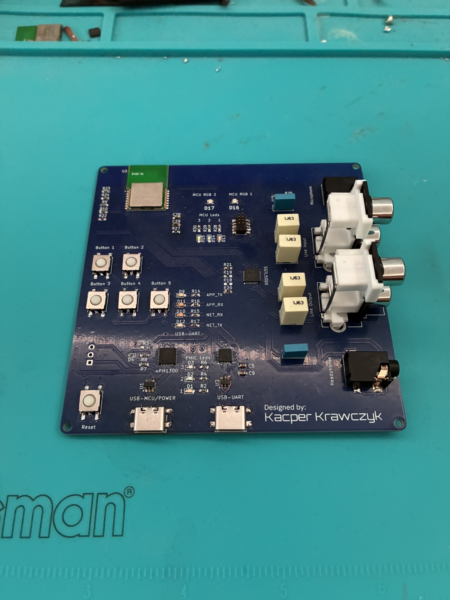
Custom hardware and firmware platform for prototyping and evaluating Bluetooth Low Energy Audio broadcast transmission.
This repository combines:
The platform is built around the BT40F SiP with the Nordic nRF5340 and was used to evaluate LE Audio broadcast transmission based on BIS streams.
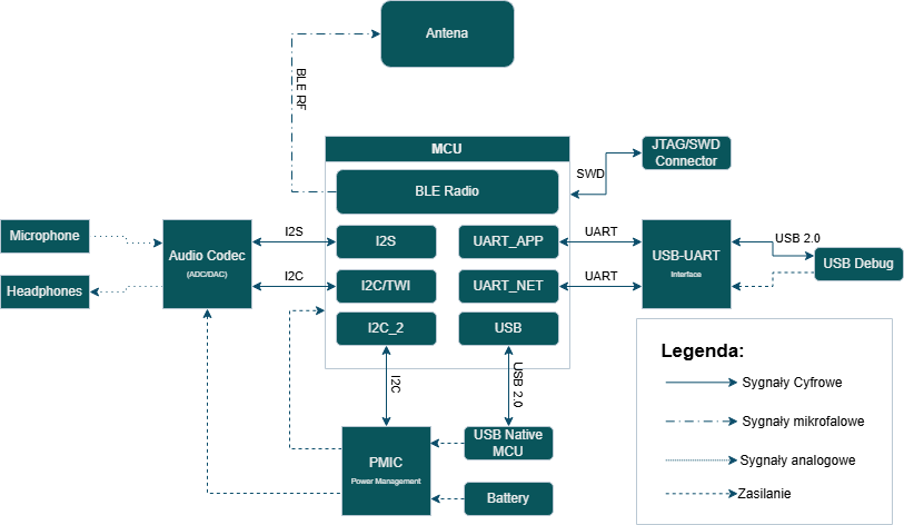
Main hardware blocks:
.
|-- Datasheets/   Component datasheets used during design and bring-up
|-- Firmware/     Zephyr/NCS applications, overlays, and helper modules
|-- Images/       Board photos, PCB renders, and architecture diagrams
|-- KiCad/        Schematic, PCB, project libraries, and Gerber outputs
`-- Tests_data/   Recorded audio samples and test logs
Important subdirectories:
Firmware/bap_broadcast_source/ BLE Audio broadcast source applicationFirmware/bap_broadcast_sink/ BLE Audio broadcast sink applicationFirmware/codec_test/ codec bring-up and audio-path verificationFirmware/test_i2c/ I2C and peripheral detection testsFirmware/leds_test/ PMIC and LED bring-upFirmware/beacon/ BLE beacon baseline applicationFirmware/biblioteki/ shared helper modules such as pmic and i2c_helpersKiCad/BT40F_audio_board_smaller/ main KiCad projectKiCad/Gerber/ exported manufacturing filesTests_data/Test_Logs/ logs from lab and real-world experimentsTests_data/Recorded_Audio/ captured audio files used during evaluationNote: some directories inside Firmware/ such as build/, Build_V1/, and MyBoard/ are generated build outputs committed alongside the source tree. They are useful as build records, but they are not the primary source files to edit.
The main project flow is built around two applications:
bap_broadcast_source transmits BLE Audio broadcast streamsbap_broadcast_sink receives BLE Audio broadcasts and contains project-specific modules for LC3 handling, USB, codec output, and stream receptionAdditional applications are included for hardware validation and bring-up:
codec_test initializes and probes the SGTL5000 pathtest_i2c verifies low-level I2C communication and peripheral presenceleds_test validates PMIC-related control paths and LED behaviorbeacon provides a minimal BLE reference applicationThe per-application README.rst files under Firmware/ are based on upstream Zephyr samples. For this repository, the project-specific behavior is defined mainly by the local src/, boards/, *.overlay, prj.conf, and Kconfig* files.
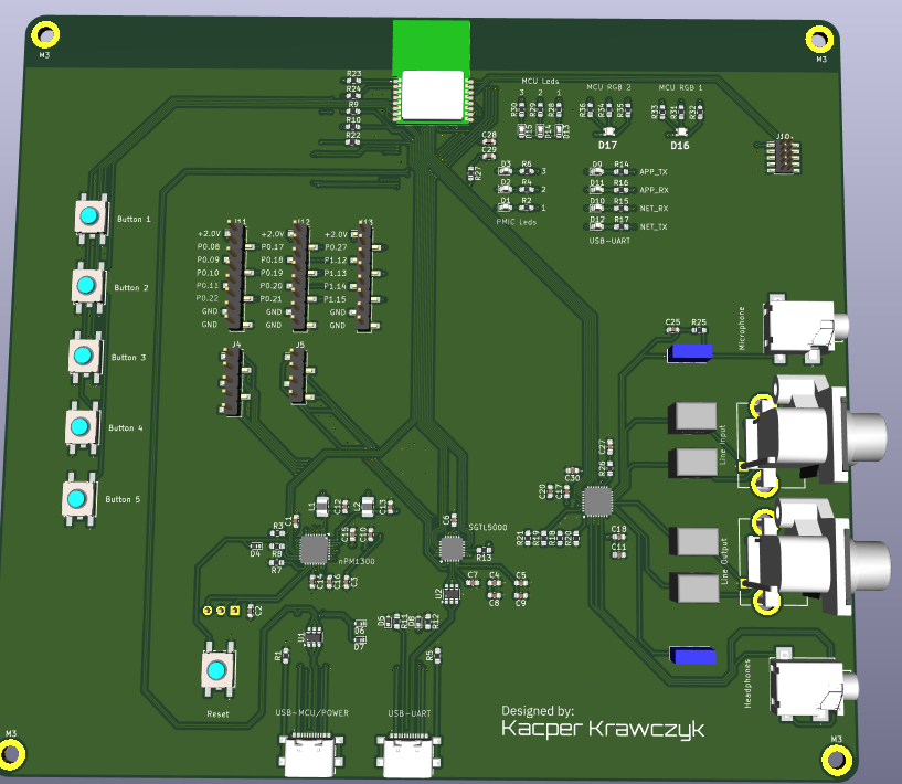
The hardware project contains:
KiCad/BT40F_audio_board_smaller/KiCad/BT40F_audio_board_smaller/Project libraries/KiCad/Gerber/BT40F_board_revA.zipImages/Some hardware files and library names still refer to nPM1300, while the assembled prototype used nPM1304 because nPM1300 was unavailable at the time. For this project, the devices are treated as near-equivalent except for the weaker charging capability of nPM1304.
This repository does not include a full NCS workspace manifest, so builds are expected to run inside an existing nRF Connect SDK environment with west available.
Example commands reconstructed from the committed build artifacts:
west build --pristine --build-dir build/source-custom Firmware/bap_broadcast_source --board nrf5340_audio_dk/nrf5340/cpuapp -- -DEXTRA_CONF_FILE=boards/nrf5340_audio_dk_nrf5340_cpuapp.conf -DCONF_FILE=prj.conf -DEXTRA_DTC_OVERLAY_FILE=Custom_Board.overlay -DDTC_OVERLAY_FILE=app.overlay

west build --pristine --build-dir build/sink-custom Firmware/bap_broadcast_sink --board nrf5340_audio_dk/nrf5340/cpuapp -- -DEXTRA_CONF_FILE=boards/nrf5340_audio_dk_nrf5340_cpuapp.conf -DCONF_FILE=prj.conf -DEXTRA_DTC_OVERLAY_FILE=Custom_Board.overlay -DDTC_OVERLAY_FILE=app.overlay

west build --pristine --build-dir build/codec-test Firmware/codec_test --board nrf5340_audio_dk/nrf5340/cpuapp -- -DCONF_FILE=prj.conf -DDTC_OVERLAY_FILE=nrf5340_audio_dk_nrf5340_cpuapp.overlay
If you build one of the custom configurations, review the local overlays and board configuration files in the target application directory before flashing.
Test artifacts are grouped under Tests_data/:
Test_Logs/01_Lab_Tests/ source and sink logs captured in laboratory conditionsTest_Logs/02_Real_World_Tests/ logs collected in a more challenging radio environmentTest_Logs/03_Audio_Transmission_test/ dedicated source and sink logs for audio transmission checksRecorded_Audio/ sample WAV capturesDue to memory constraints, logging on the Network Core was disabled. The provided logs come from the Application Core.
This project is licensed under the terms of the LICENSE file in this repository.
| Qty | Value | Footprint | References |
|---|---|---|---|
| 10 | 160 | Resistor_SMD:R_0603_1608Metric_Pad0.98x0.95mm_HandSolder | R2, R4, R6, R14, R15, R16, R17, R28, R29, R30 |
| 9 | 0 | Resistor_SMD:R_0603_1608Metric_Pad0.98x0.95mm_HandSolder | R1, R3, R5, R18, R19, R20, R21, R22, R26 |
| 8 | 10uF | Capacitor_SMD:C_0603_1608Metric_Pad1.08x0.95mm_HandSolder | C4, C10, C11, C12, C13, C14, C15, C17 |
| 7 | LED | LED_SMD:LED_0603_1608Metric_Pad1.05x0.95mm_HandSolder | D1, D2, D3, D9, D10, D11, D12 |
| 6 | 0.1uF | Capacitor_SMD:C_0603_1608Metric_Pad1.08x0.95mm_HandSolder | C7, C9, C18, C20, C27, C30 |
| 5 | 1uF | Capacitor_SMD:C_0603_1608Metric_Pad1.08x0.95mm_HandSolder | C3, C8, C16, C25, C28 |
| 5 | 2k2 | Resistor_SMD:R_0603_1608Metric_Pad0.98x0.95mm_HandSolder | R9, R10, R23, R24, R27 |
| 5 | ESD | Diode_SMD:D_SOD-523 | D4, D5, D6, D7, D8 |
| 4 | 1uF | External_footprints:R82_cap_raster_5mm | C21, C22, C23, C24 |
| 2 | 0.1uF | External_footprints:Cap_foil_5mm | C19, C26 |
| 2 | 140 | Resistor_SMD:R_0603_1608Metric_Pad0.98x0.95mm_HandSolder | R33, R36 |
| 2 | 180 | Resistor_SMD:R_0603_1608Metric_Pad0.98x0.95mm_HandSolder | R32, R35 |
| 2 | 2.2uH | Inductor_SMD:L_1008_2520Metric_Pad1.43x2.20mm_HandSolder | L1, L2 |
| 2 | 340 | Resistor_SMD:R_0603_1608Metric_Pad0.98x0.95mm_HandSolder | R31, R34 |
| 2 | 4.7uF | Capacitor_SMD:C_0603_1608Metric_Pad1.08x0.95mm_HandSolder | C6, C29 |
| 2 | 5.1k | Resistor_SMD:R_0603_1608Metric_Pad0.98x0.95mm_HandSolder | R11, R12 |
| 2 | AudioJack3 | External_footprints:35RASMT2BHWNTRX | J6, J9 |
| 2 | Conn_Coaxial_x2 | External_footprints:FC68405 | J7, J8 |
| 2 | LED_2 | LED_SMD:LED_0603_1608Metric_Pad1.05x0.95mm_HandSolder | D14, D15 |
| 2 | USBLC6-2SC6 | Package_TO_SOT_SMD:SOT-23-6 | U1, U2 |
| 1 | 1-5uF | Capacitor_SMD:C_0603_1608Metric_Pad1.08x0.95mm_HandSolder | C5 |
| 1 | 100nF | Capacitor_SMD:C_0603_1608Metric_Pad1.08x0.95mm_HandSolder | C1 |
| 1 | 2.2k | Resistor_SMD:R_0603_1608Metric_Pad0.98x0.95mm_HandSolder | R25 |
| 1 | 2.2uF | Capacitor_SMD:C_0603_1608Metric_Pad1.08x0.95mm_HandSolder | C2 |
| 1 | 4.7k | Resistor_SMD:R_0603_1608Metric_Pad0.98x0.95mm_HandSolder | R13 |
| 1 | 500k | Resistor_SMD:R_0603_1608Metric_Pad0.98x0.95mm_HandSolder | R8 |
| 1 | 68k | Resistor_SMD:R_0603_1608Metric_Pad0.98x0.95mm_HandSolder | R7 |
| 1 | BTN1 | External_footprints:EVQQ2D02W | SW2 |
| 1 | BTN2 | External_footprints:EVQQ2D02W | SW3 |
| 1 | BTN3 | External_footprints:EVQQ2D02W | SW4 |
| 1 | BTN4 | External_footprints:EVQQ2D02W | SW5 |
| 1 | BTN5 | External_footprints:EVQQ2D02W | SW6 |
| 1 | CP2105-F01-GM | External_footprints:CP2105-F01-GM | IC2 |
| 1 | Conn_01x03_Pin | Connector_PinHeader_2.54mm:PinHeader_1x03_P2.54mm_Horizontal | J3 |
| 1 | Conn_01x04_Socket | Connector_PinHeader_2.54mm:PinHeader_1x04_P2.54mm_Vertical_SMD_Pin1Left | J5 |
| 1 | Conn_01x05_Socket | Connector_PinHeader_2.54mm:PinHeader_1x05_P2.54mm_Vertical_SMD_Pin1Left | J4 |
| 1 | Conn_ARM_JTAG_SWD_10 | Connector_PinHeader_1.27mm:PinHeader_2x05_P1.27mm_Vertical_SMD | J10 |
| 1 | LED_1 | LED_SMD:LED_0603_1608Metric_Pad1.05x0.95mm_HandSolder | D13 |
| 1 | NPM1300-QEAA-R7 | External_footprints:NPM1300-QEAA-R7 | IC1 |
| 1 | R1 | Connector_PinHeader_2.54mm:PinHeader_1x08_P2.54mm_Vertical_SMD_Pin1Left | J11 |
| 1 | R2 | Connector_PinHeader_2.54mm:PinHeader_1x08_P2.54mm_Vertical_SMD_Pin1Left | J12 |
| 1 | R3 | Connector_PinHeader_2.54mm:PinHeader_1x08_P2.54mm_Vertical_SMD_Pin1Left | J13 |
| 1 | RGB_1 | External_footprints:OSTB0603C1CA | D16 |
| 1 | RGB_2 | External_footprints:OSTB0603C1CA | D17 |
| 1 | SGTL5000XNBA3R2 | External_footprints:SGTL5000XNBA3R2 | IC3 |
| 1 | SW_Push | External_footprints:EVQQ2D02W | SW1 |
| 1 | USB_C_Core | External_footprints:USB421603A | J1 |
| 1 | USB_C_Debug | External_footprints:USB421603A | J2 |
| 1 | ~ | External_footprints:XCVR_BT40F | U3 |
The 110 most common of 114 parts.

Randomwaves/Drumboy-Pro
📖 Developer Wiki — full hardware specs, schematics walkthrough, firmware architecture, DSP internals, and memory map.

ColbyDAllen/Wearable-Drum-Machine
This project is mostly complete. Until I can find a more suitable input/sensory solution, please consider this work on hiatus.


kitspace-forks/air-quality-monitor
Design repository for an ESP32-based IoT air quality monitor


jadenrhee/JRWatch
Low-power BLE wearable: nRF52840 module + nPM1300 PMIC + BMI270 IMU + Sharp MIP display. 36 mm 4-layer board, ~15 µA projected sleep current, Zephyr firmware.

NEOgHacking/DMXion_4Port_Node
A 4 port dmx node with rdm funtionallity. Connects via ARTNET or sACN
It measures 100 × 100 mm and has 4 copper layers, 1.6 mm thick.
114 parts, built around the CP2105-F01-GM, SGTL5000XNBA3R2, USBLC6-2SC6 and NPM1300-QEAA-R7. The full list of its parts is on this page, with links to each part's symbol and footprint where PCBKit's library has them.
From the KapiCola/ble-audio-platform repository on GitHub, at the commit this page was made from: the board is KiCad/BT40F_audio_board_smaller/BT40F_audio_board.kicad_pcb and its schematic KiCad/BT40F_audio_board_smaller/BT40F_audio_board.kicad_sch. PCBKit opens the board in the browser, with nothing to install.
Its repository publishes it under the MIT licence: you may reuse it on that licence's terms (keep the author's notice, and for a copyleft licence share your changes alike).