2 layers145 × 75 mm
EC DLM-001-Rev3
kevinisabelle/litdlm01
AVR C Drum Lighting module using XMEGA microcontroller (Includes KiCad PCB)
88 parts

 Kaelor9/Marine-RGB-Light-Controller
Marine RGB Light Controller
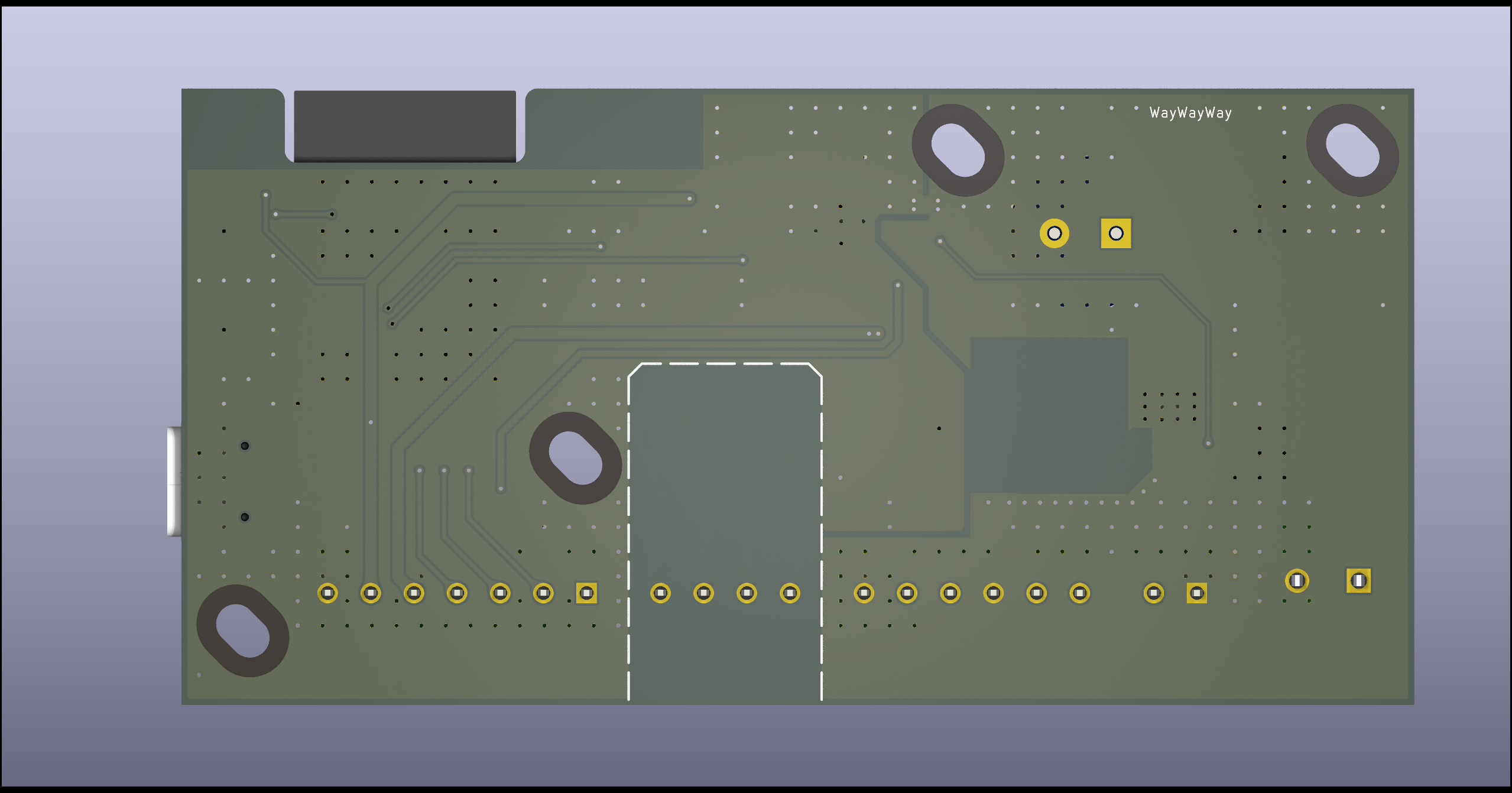
Marine RGB Light Controller is an open-source printed circuit board by Kaelor9, from the Kaelor9/Marine-RGB-Light-Controller repository on GitHub. It is a 2-layer board of 100 × 50 mm with 98 parts on 85 nets, routed with 287 tracks and 330 vias.
It is built around the ESP32-S3-WROOM-1-N8R8, SN74AHCT125QDRQ1 and USBLC6-2SC6. Its parts include 31 capacitors, 23 resistors, 16 diodes, 7 ICs and 6 connectors. It belongs with the lEDs and displays boards and the ESP32 boards of this library.


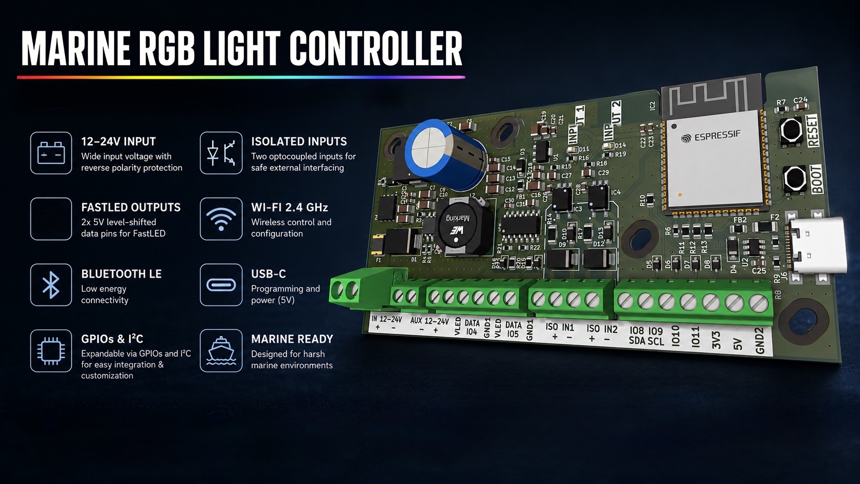
Professional ESP32-S3 controller for addressable RGB LED installations in marine, automotive and industrial environments.






The Marine RGB Light Controller is a custom-designed ESP32-S3 controller developed for reliable operation in demanding electrical environments.
Unlike generic ESP32 development boards, it integrates protected power electronics, optically isolated inputs, dual level-shifted LED outputs and dedicated expansion interfaces into a single compact PCB.
Originally designed for marine lighting systems, the controller is equally suited for automotive, off-road, RV, architectural and industrial LED installations.
Most ESP32 development boards are intended for prototyping and require additional external circuitry before they are suitable for real-world installations.
The Marine RGB Light Controller integrates the essential hardware needed for reliable field deployment:
This significantly reduces external wiring while improving robustness and long-term reliability.
The controller is suitable for a wide range of professional LED installations, including:
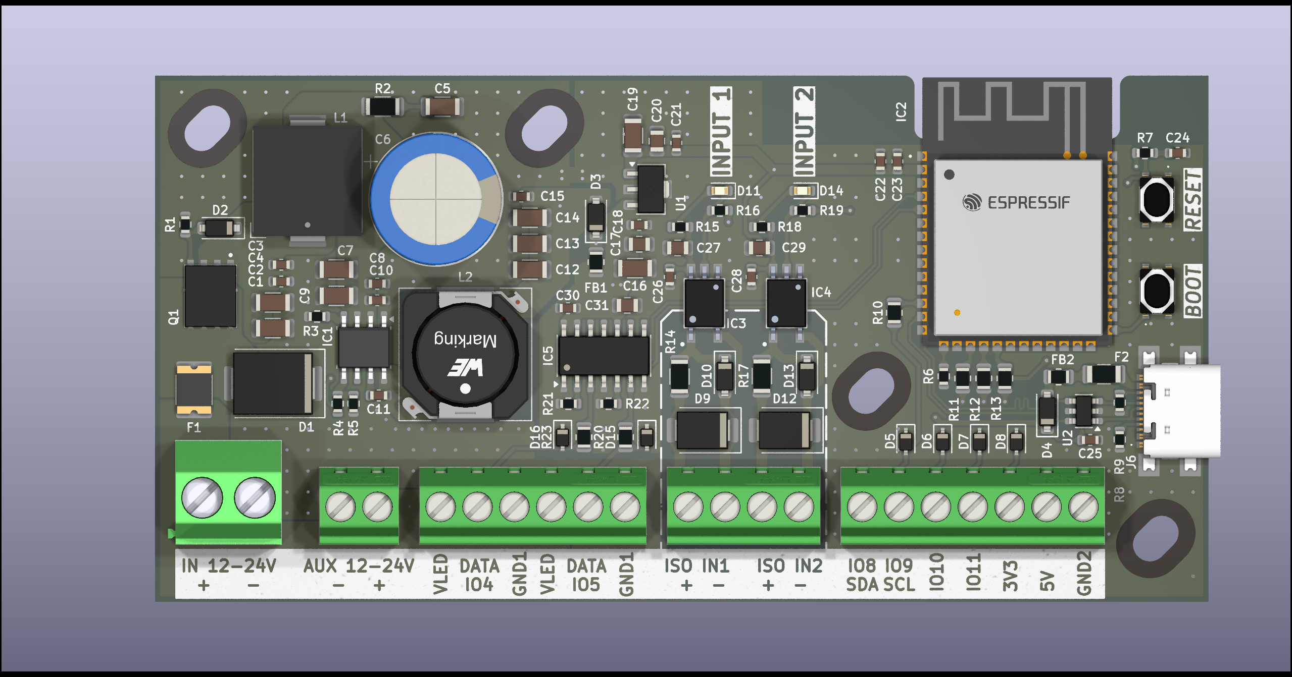
The PCB integrates everything required for a professional LED controller:
| Feature | Specification |
|---|---|
| MCU | ESP32-S3-WROOM-1-N8R8 |
| Flash | 8 MB |
| PSRAM | 8 MB |
| Input Voltage | 12–24V DC |
| Controller Protection | Fuse + Reverse Polarity + TVS |
| LED Supply | Direct VIN Pass-through |
| LED Outputs | 2 × 5V Logic (Level Shifted) |
| Digital Inputs | 2 × Optically Isolated |
| Wireless | Wi-Fi 2.4 GHz + Bluetooth LE |
| USB | USB-C |
| Expansion | GPIO + I²C |
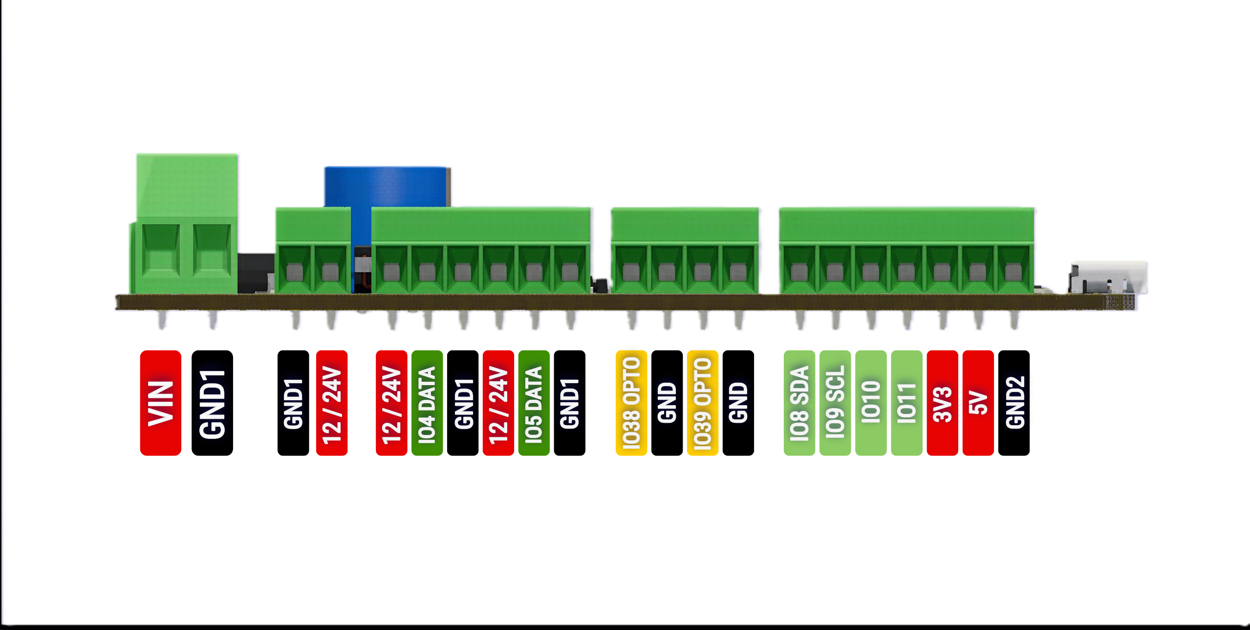
| Connection | Function |
|---|---|
| VIN | 12–24V DC Input |
| AUX Power | Direct VIN Pass-through |
| DATA 1 | 5V LED Data Output |
| DATA 2 | 5V LED Data Output |
| ISO IN1 | Optically Isolated Input |
| ISO IN2 | Optically Isolated Input |
| SDA / SCL | I²C Expansion |
| IO8 / IO9 | GPIO Expansion |
| IO10 / IO11 | GPIO Expansion |
| 3V3 | 3.3V Output |
| 5V | 5V Output |
| GND | Ground |
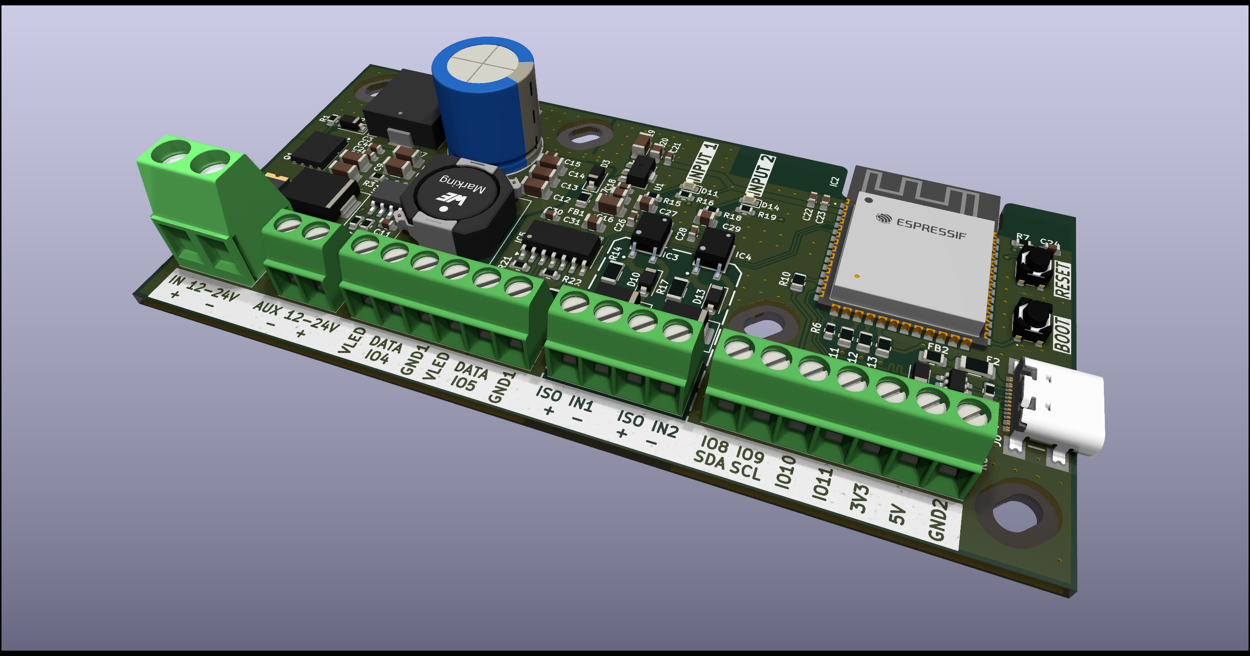
The firmware is developed for the ESP32-S3 using the Arduino framework and is designed around a modern, responsive web interface.
Configuration is performed directly from any web browser without requiring additional software. The modular firmware architecture allows new LED effects and features to be added easily.
Current and planned features include:
.
├── docs/
│   ├── images/
│   ├── hardware.md
│   ├── software.md
│   └── fabrication.md
│
├── firmware/
│   └── Marine_RGB_Controller/
│
├── hardware/
│   ├── kicad/
│   ├── fabrication/
│   └── 3d/
│
├── site/
│
├── LICENSE
└── README.mdProject documentation is located inside the docs directory.
Available documentation includes:
[!IMPORTANT]
The LED power output is a direct pass-through of the input supply voltage.
- LED VOUT = VIN
- The LED supply is not reverse polarity protected
- The LED supply is not fused
- Only the controller electronics are protected by the onboard fuse, TVS diode and reverse polarity protection
- External protection should be added where required by the installation
| Hardware | Firmware | Documentation |
|---|---|---|
| ✅ Revision 1 Complete | 🚧 In Development | 🚧 In Progress |
This project is proprietary.
Copyright © 2026 Anders Merrild
All rights reserved.
No permission is granted to copy, modify, distribute, manufacture, publish, sublicense or use any part of this project without prior written permission from the copyright holder.
See the LICENSE file for full terms.
Designed and developed by Kaelor9
ESP32 • Marine Electronics • Professional RGB Lighting Controller
| Qty | Value | Footprint | References |
|---|---|---|---|
| 13 | 100nF | Capacitor_SMD:C_0603_1608Metric | C3, C4, C8, C10, C11, C15, C18, C21, C23, C25, C26, C28, C30 |
| 6 | 220R | Resistor_SMD:R_0805_2012Metric | R10, R11, R12, R13, R20, R23 |
| 6 | SD05_SOD323 | Diode_SMD:D_SOD-323 | D5, D6, D7, D8, D15, D16 |
| 5 | 1uF | Capacitor_SMD:C_0805_2012Metric | C17, C20, C27, C29, C31 |
| 3 | 100K | Resistor_SMD:R_0603_1608Metric | R1, R21, R22 |
| 3 | 10k | Resistor_SMD:R_0603_1608Metric | R5, R6, R7 |
| 3 | 22uF | Capacitor_SMD:C_1206_3216Metric | C12, C13, C14 |
| 3 | 4.7uF | Capacitor_SMD:C_1206_3216Metric | C5, C7, C9 |
| 2 | 100R | Resistor_SMD:R_0603_1608Metric | R16, R19 |
| 2 | 10uF | Capacitor_SMD:C_1206_3216Metric | C16, C19 |
| 2 | 10uF | Capacitor_SMD:C_0603_1608Metric | C22, C24 |
| 2 | 2.2k | Resistor_SMD:R_0603_1608Metric | R15, R18 |
| 2 | 2.2uF | Capacitor_SMD:C_1206_3216Metric | C1, C2 |
| 2 | 2.7K | Resistor_SMD:R_1206_3216Metric | R14, R17 |
| 2 | 5.1K | Resistor_SMD:R_0603_1608Metric | R8, R9 |
| 2 | D_Schottky | Diode_SMD:D_SOD-123 | D3, D4 |
| 2 | D_TVS | Diode_SMD:D_SMB | D9, D12 |
| 2 | LED | LED_SMD:LED_0603_1608Metric | D11, D14 |
| 2 | NetTie_2 | NetTie:NetTie-2_SMD_Pad0.5mm | NT1, NT1 |
| 2 | TLP2361_TPL,E | Added Components:SOIC-6 | IC3, IC4 |
| 2 | ~ | Diode_SMD:D_SOD-123 | D10, D13 |
| 2 | ~ | Added Components:SW [PTS810SJM250SMTRLFS] | BOOT, RESET |
| 1 | |||
| 1 | 1.5A | Fuse:Fuse_1812_4532Metric | F1 |
| 1 | 10 µH | Inductor_SMD:L_12x12mm_H6mm | L2 |
| 1 | 10uH | Inductor_SMD:L_Bourns_SRP1038C_10.0x10.0mm | L1 |
| 1 | 2.2Ω | Resistor_SMD:R_1206_3216Metric | R2 |
| 1 | 40.2k | Resistor_SMD:R_0603_1608Metric | R4 |
| 1 | 470uF | Capacitor_THT:CP_Radial_D12.5mm_P5.00mm | C6 |
| 1 | 64.9k | Resistor_SMD:R_0603_1608Metric | R3 |
| 1 | AP7365-33YG-13 | Package_TO_SOT_SMD:SOT-89-3 | U1 |
| 1 | BLM21PG600SN1D | Resistor_SMD:R_0805_2012Metric | FB1 |
| 1 | C | Package_SO:Texas_R-PDSO-G8_EP2.95x4.9mm_Mask2.4x3.1mm | IC1 |
| 1 | D_TVS | Diode_SMD:D_SMC | D1 |
| 1 | D_Zener_Filled | Diode_SMD:D_SOD-123 | D2 |
| 1 | ESP32-S3-WROOM-1-N8R8 | Added Components:ESP32S3WROOM1N8R8 | IC2 |
| 1 | FerriteBead_Small | Resistor_SMD:R_0805_2012Metric | FB2 |
| 1 | PMOS | Added Components:P-MOS [SI7141DPT1GE3] | Q1 |
| 1 | Polyfuse | Fuse:Fuse_1206_3216Metric | F2 |
| 1 | SN74AHCT125QDRQ1 | Package_SO:SOIC-14_3.9x8.7mm_P1.27mm | IC5 |
| 1 | Screw_Terminal_01x02 | Added Components:2_Position Screw Terminal 5mm Pitch | J5 |
| 1 | Screw_Terminal_01x02 | Added Components:Fixed Terminal Blocks 2P 3.5mm 0DEG | J2 |
| 1 | Screw_Terminal_01x04 | Added Components:Fixed Terminal Blocks 4P 3.5mm 90DEG | J3 |
| 1 | Screw_Terminal_01x06 | Added Components:Fixed Terminal Blocks 6P 3.5mm 90DEG | J4 |
| 1 | Screw_Terminal_01x07 | Added Components:Fixed Terminal Blocks 7P 3.5mm 90DEG | J1 |
| 1 | USBLC6-2SC6 | Package_TO_SOT_SMD:SOT-23-6 | U2 |
| 1 | USB_C_Receptacle_USB2.0_16P | Added Components:USB C [USB494000A] | J6 |
The 95 most common of 98 parts.
kevinisabelle/litdlm01
AVR C Drum Lighting module using XMEGA microcontroller (Includes KiCad PCB)


punkfab/pcb-corpus
235 real KiCad boards from open-source hardware repositories, prepared as a placement and routing benchmark

itsmevjnk/MelbourneTrainTracker
Melbourne Train Tracker project repository (SIT210, T1/2025)


pulikantitarun/redcat51ii-automated-flat-panel
Automated flat panel controller, PCB, firmware, and 3D-printable hardware for the William Optics RedCat 51 II and ASIAIR Plus
It measures 100 × 50 mm and has 2 copper layers, 1.6 mm thick.
98 parts, built around the ESP32-S3-WROOM-1-N8R8, SN74AHCT125QDRQ1 and USBLC6-2SC6. The full list of its parts is on this page, with links to each part's symbol and footprint where PCBKit's library has them.
From the Kaelor9/Marine-RGB-Light-Controller repository on GitHub, at the commit this page was made from: the board is hardware/kicad/Marine RGB Light Controller.kicad_pcb and its schematic hardware/kicad/Marine RGB Light Controller.kicad_sch. PCBKit opens the board in the browser, with nothing to install.
Its repository states no licence, so its author keeps all rights: ask Kaelor9 before reusing the design.