

2 layers254 × 160 mm

 KabukiFlux/MIDI4MiSTer13
MiSTer user port MIDI output and input PCB
MIDI4MiSTer is an open-source printed circuit board by KabukiFlux, from the KabukiFlux/MIDI4MiSTer repository on GitHub, published under the MIT licence. It is a 2-layer board of 44 × 44.8 mm with 40 parts on 38 nets, routed with 227 tracks and 9 vias.
It is built around the 74HC14 and AMS1117. Its parts include 12 resistors, 4 capacitors, 4 diodes, 3 ICs and 3 connectors. It belongs with the audio and music boards of this library.
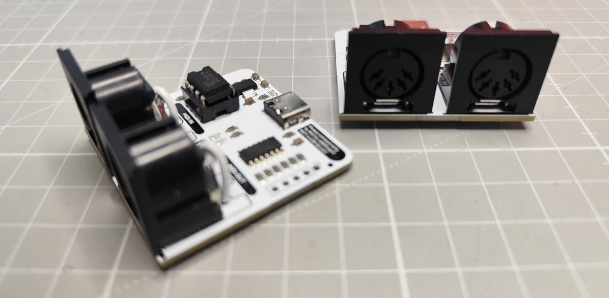
This repository contains the KiCAD project files for a custom MIDI Interface
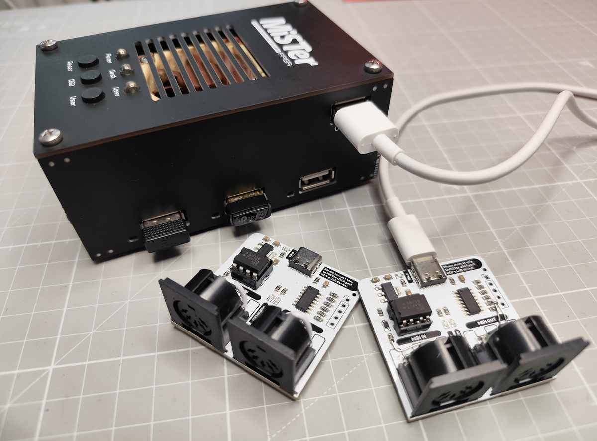
Board, designed to connect to the User IO port of the MiSTer FPGA.
It enables MIDI input and output functionality for cores that support MIDI,
including the Atari ST, X68000, PC, and Minimig.
The goal of this project is to provide a simple and reliable way to connect external MIDI hardware (keyboards, synthesizers, modules) to the MiSTer FPGA platform.
If you enjoy exploring the full capabilities of MiSTer cores such as the Atari ST, Minimig, ao486 (PC) or X68000 with authentic MIDI input/output, this board makes it possible.
MiSTer already supports MIDI in several cores, but connecting external gear requires
proper electrical isolation and signal compliance with the MIDI standard.
This board provides exactly that:
This design does not emulate MIDI or add new core support—it acts as a hardware bridge for existing MiSTer MIDI features.
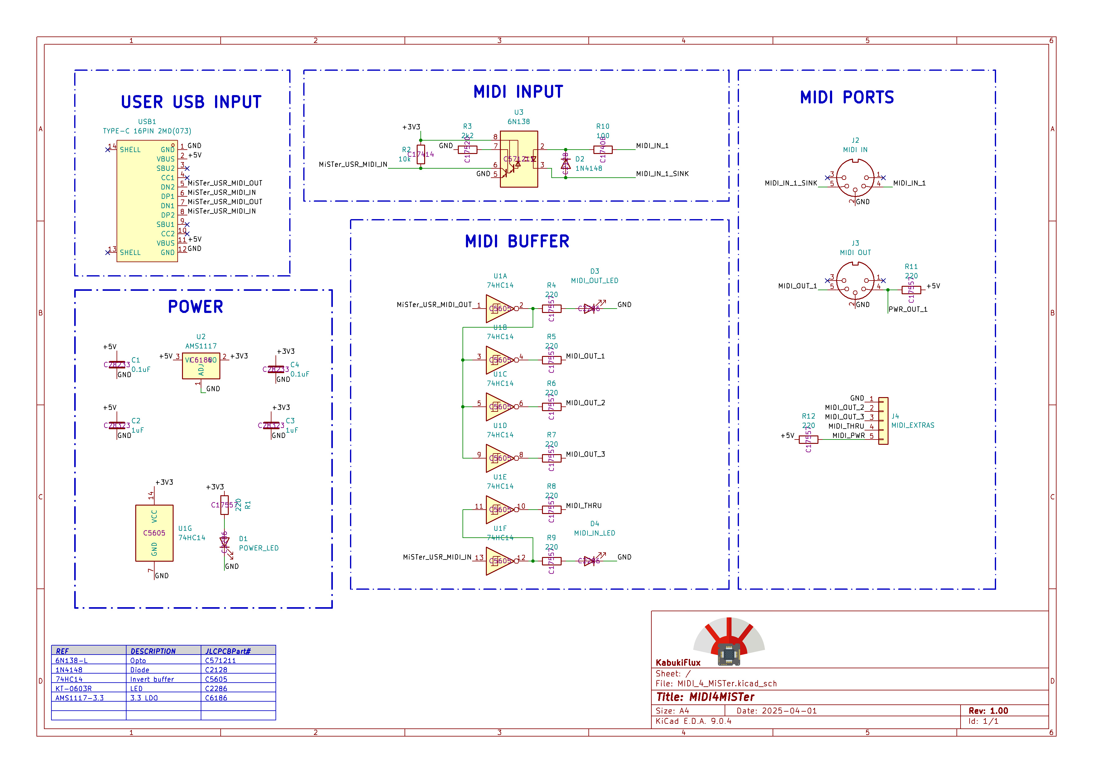
This is the schematics:
/gerbers/) to a PCB manufacturer such as
JLCPCB or your preferred supplier.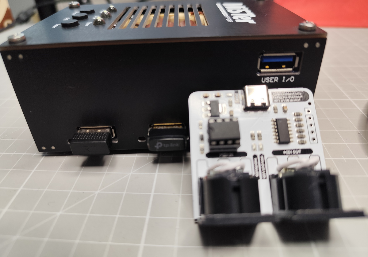

/kicad/ – KiCAD design files for the MIDI Interface Board/bom/ – Circuit parts and assembly guide/gerbers/ – Gerber files for PCB fabrication/assets/ – Images of schematics, renders, and assembled boardNo liability is assumed for misuse or damage.
See LICENSE for more information.
This project is intended for hobbyist and educational purposes.
Use at your own risk. The MiSTer FPGA and connected MIDI hardware must
be in good working condition before use. This repository is not affiliated with MiSTer project developers but we support them.
The 3D models and footprints belong to each license holder.
| Qty | Value | Footprint | References |
|---|---|---|---|
| 9 | 220 | Resistor_SMD:R_0805_2012Metric_Pad1.20x1.40mm_HandSolder | R1, R4, R5, R6, R7, R8, R9, R11, R12 |
| 2 | 0.1uF | Capacitor_SMD:C_0805_2012Metric_Pad1.18x1.45mm_HandSolder | C1, C4 |
| 2 | 1uF | Capacitor_SMD:C_0805_2012Metric_Pad1.18x1.45mm_HandSolder | C2, C3 |
| 1 | 100 | Resistor_SMD:R_0805_2012Metric_Pad1.20x1.40mm_HandSolder | R10 |
| 1 | 10k | Resistor_SMD:R_0805_2012Metric_Pad1.20x1.40mm_HandSolder | R2 |
| 1 | 1N4148 | Diode_SMD:D_SOD-323_HandSoldering | D2 |
| 1 | 2k2 | Resistor_SMD:R_0805_2012Metric_Pad1.20x1.40mm_HandSolder | R3 |
| 1 | 6N138 | Package_DIP:DIP-8_W7.62mm_LongPads | U3 |
| 1 | 74HC14 | Package_SO:SOIC-14_3.9x8.7mm_P1.27mm | U1 |
| 1 | AMS1117 | Package_TO_SOT_SMD:SOT-223-3_TabPin2 | U2 |
| 1 | G*** | kibuzzard-67F91168 | kibuzzard-67F91168 |
| 1 | G*** | kibuzzard-67F911FC | kibuzzard-67F911FC |
| 1 | G*** | kibuzzard-67F9106B | kibuzzard-67F9106B |
| 1 | G*** | kibuzzard-67F91062 | kibuzzard-67F91062 |
| 1 | G*** | kibuzzard-67F91059 | kibuzzard-67F91059 |
| 1 | G*** | kibuzzard-67F91733 | kibuzzard-67F91733 |
| 1 | G*** | kibuzzard-67F912C1 | kibuzzard-67F912C1 |
| 1 | G*** | kibuzzard-67F91050 | kibuzzard-67F91050 |
| 1 | G*** | kibuzzard-67F911EE | kibuzzard-67F911EE |
| 1 | G*** | kibuzzard-67F91074 | kibuzzard-67F91074 |
| 1 | G*** | kibuzzard-67F91142 | kibuzzard-67F91142 |
| 1 | G*** | kibuzzard-67F9113A | kibuzzard-67F9113A |
| 1 | LOGO | library:LogoKabuki_18mm | G01 |
| 1 | MIDI IN | library:MIDI_DIN5 | J2 |
| 1 | MIDI OUT | library:MIDI_DIN5 | J3 |
| 1 | MIDI_EXTRAS | Connector_PinHeader_2.54mm:PinHeader_1x05_P2.54mm_Vertical | J4 |
| 1 | MIDI_IN_LED | LED_SMD:LED_0603_1608Metric | D4 |
| 1 | MIDI_OUT_LED | LED_SMD:LED_0603_1608Metric | D3 |
| 1 | POWER_LED | LED_SMD:LED_0603_1608Metric | D1 |
| 1 | TYPE-C 16PIN 2MD(073) | C2765186:USB-C-SMD_TYPE-C-6PIN-2MD-073 | USB1 |


AlessandroAU/Chorus32-ESP32LapTimer
This is an ESP32 port of the popular Chorus RF Laptimer


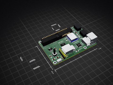
uli/basicengine-pcb
Schematics and PCB layout for the BASIC Engine home computer

It measures 44 × 44.8 mm and has 2 copper layers, 1.6 mm thick.
40 parts, built around the 74HC14 and AMS1117. The full list of its parts is on this page, with links to each part's symbol and footprint where PCBKit's library has them.
From the KabukiFlux/MIDI4MiSTer repository on GitHub, at the commit this page was made from: the board is kicad/MIDI_4_MiSTer.kicad_pcb and its schematic kicad/MIDI_4_MiSTer.kicad_sch. PCBKit opens the board in the browser, with nothing to install.
Its repository publishes it under the MIT licence: you may reuse it on that licence's terms (keep the author's notice, and for a copyleft licence share your changes alike).