
2 layers58.4 × 53.3 mm
Rf cc1101
josevas72/rf-cc1101-esp32
Emisor/receptor RF 433 MHz con ESP32 + CC1101 para Home Assistant (PCB KiCad, ESPHome, caja 3D)
8 parts3MIT
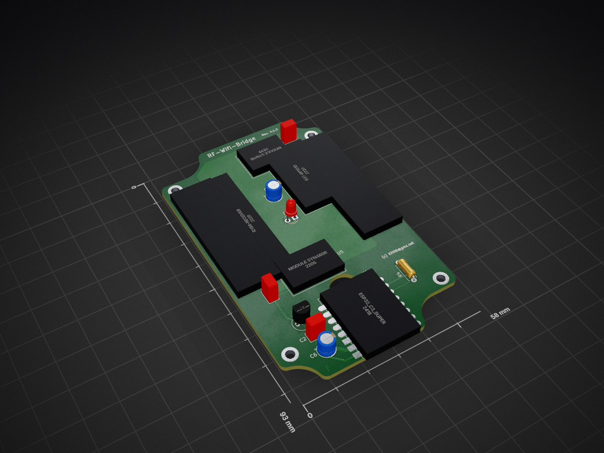
 KHit6/RF-WiFi-Bridge
A simple hardware design to bridge between 433 MHz devices and WiFi
RF WiFi Bridge is an open-source printed circuit board by KHit6, from the KHit6/RF-WiFi-Bridge repository on GitHub, published under the CERN-OHL-W-2.0 licence. It is a 2-layer board of 58 × 93 mm with 20 parts on 25 nets, routed with 161 tracks and 9 vias.
It is built around the E07-M1101D-TH. Its parts include 7 ICs, 5 capacitors, 1 resistor and 1 diode. It belongs with the radio and wireless and home automation and IoT boards and the ESP32 and RISC-V boards of this library.
Also it should be a replacement for Sonoff's RF-Bridge. RF-Bridge mostly must be hardware modified and lacks an easy way to directly install a custom firmware. Shortly, it is complicated in use.
My main goal was to receive sensor data from low cost TFA (or LaCrosse) 433 Mhz temperature and humidity sensors to use the data with ESPHOME and Home Assistant. The companion repository rf-sensor-bridge (previous tfagateway) provides the open source code base to receive data from such sensors.
With the module from Ebyte you can use the provided PCB-antenna or the antenna assembled with your module. Unfortunately, if using the PCB-Antenna you have to remove the previous antenna from the module and connect the antenna trace to the PCB-antenna via the provided drillhole. If you like to fasten the CC1101 module with screws you must take plastic screws and nuts.
Please consider LICENSE.txt
This project wouldn't be possible without KiCad . KiCad is a great tool.
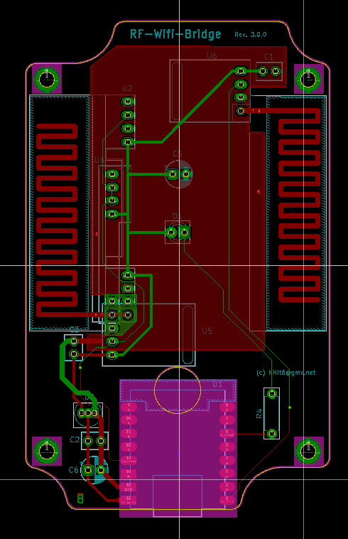
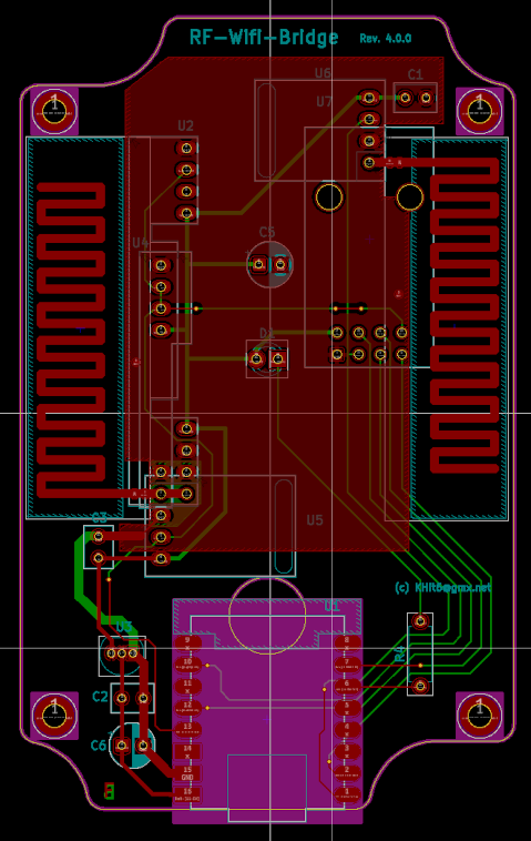
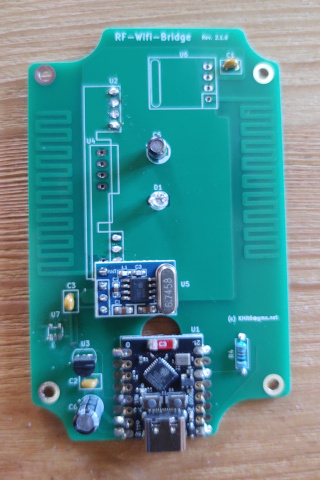
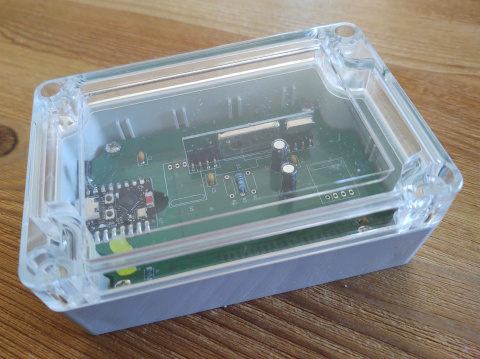
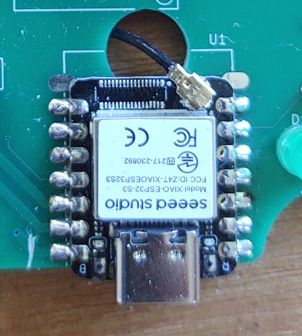
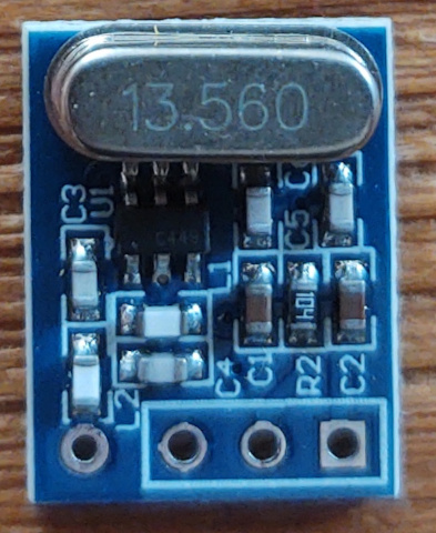
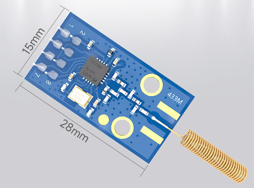
(c) 2026 KHit6
| Qty | Value | Footprint | References |
|---|---|---|---|
| 4 | Housing_Pad | MountingHole:MountingHole_2.7mm_M2.5_DIN965_Pad_TopBottom | N1, N2, N3, N4 |
| 3 | 100n | Capacitor_THT:C_Rect_L4.6mm_W3.0mm_P2.50mm_MKS02_FKP02 | C1, C2, C3 |
| 2 | 100u | Capacitor_THT:CP_Radial_D5.0mm_P2.50mm | C5, C6 |
| 2 | Meander_Antenna | Antennas:433MHz_Meander_Antenna_left | AE1, AE2 |
| 1 | 1k | Resistor_THT:R_Axial_DIN0207_L6.3mm_D2.5mm_P7.62mm_Horizontal | R4 |
| 1 | E07-M1101D | RF_Modules:E07-M1101D-Tranceiver_THT | U7 |
| 1 | ESP32_C3_Supermini | ESP_Modules:ESP32_C3_Supermini_SMD | U1 |
| 1 | LED gn | LED_THT:LED_D3.0mm | D1 |
| 1 | MCP1702-330xxTO | Package_TO_SOT_THT:TO-92_Inline | U3 |
| 1 | Module RXB12 SYN470R | RF_Modules:RXB12_Receiver_SYN470R_THT | U4 |
| 1 | Module SYN115 | RF_Modules:SYN115_Transmitter_THT | U6 |
| 1 | Module SYN480R | RF_Modules:SYN480R_Receiver_THT | U5 |
| 1 | RXB6-Receiver | RF_Modules:RXB6_Receiver_THT | U2 |
josevas72/rf-cc1101-esp32
Emisor/receptor RF 433 MHz con ESP32 + CC1101 para Home Assistant (PCB KiCad, ESPHome, caja 3D)

gjcourt/lab
A curated list of 140 multidisciplinary engineering and skill-building projects


atopile/atopile
Design circuit boards with code! ✨ Get software-like design reuse 🚀, validation, version control and collaboration in hardware; starting with electronics ⚡️

davidphilipbarr/Sweep
Sweep - a small promicro based keyboard inspired by the Ferris.

rusefi/rusefi
rusefi - GPL internal combustion engine control unit
It measures 58 × 93 mm and has 2 copper layers, 1.6 mm thick.
20 parts, built around the E07-M1101D-TH. The full list of its parts is on this page, with links to each part's symbol and footprint where PCBKit's library has them.
From the KHit6/RF-WiFi-Bridge repository on GitHub, at the commit this page was made from: the board is RF-Wifi-Bridge.kicad_pcb and its schematic RF-Wifi-Bridge-01.kicad_sch. PCBKit opens the board in the browser, with nothing to install.
Its repository publishes it under the CERN-OHL-W-2.0 licence: you may reuse it on that licence's terms (keep the author's notice, and for a copyleft licence share your changes alike).