

4 layers70 × 72 mm

 JubilantMarmot/HC-pcbcalc
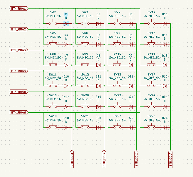
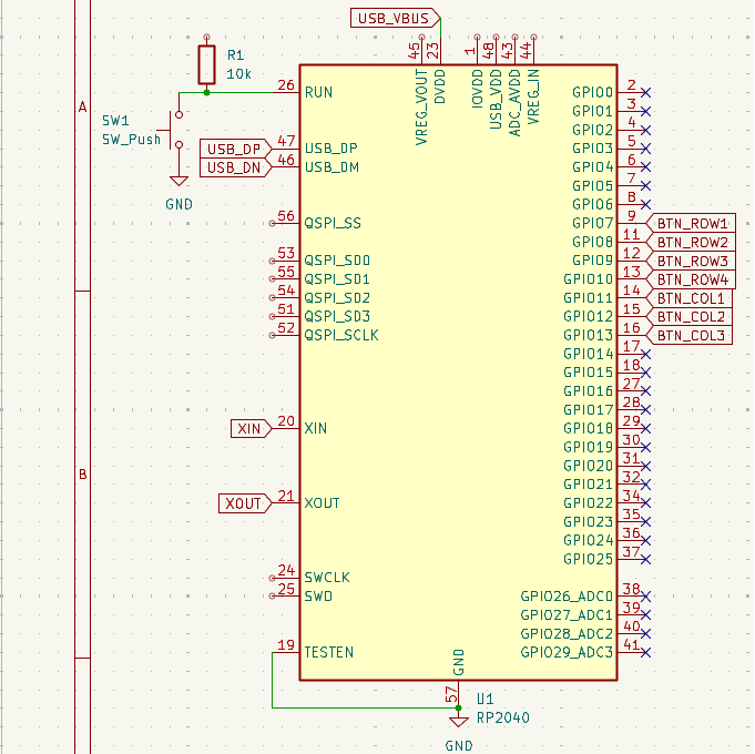
This is a button matrix schematic that uses RP2040 to connect to GPIO pins in an efficient manner.
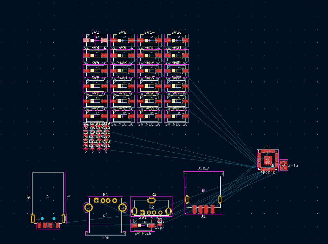
Calculator is an open-source printed circuit board by JubilantMarmot, from the JubilantMarmot/HC-pcbcalc repository on GitHub. It is a 2-layer board with 57 parts on 79 nets.
It is built around the RP2040 and ABM8-272-T3. Its parts include 25 switches, 24 diodes, 3 resistors, 2 capacitors and 1 IC. It belongs with the RP2040 boards of this library.
This is a button matrix schematic that uses RP2040 to connect to GPIO pins in an efficient manner.
As an example, I also implemented a calculator with Reverse Polish Notation (RPN) using the GPIO pins.
I originally was going to make this into an actual project, but I failed with the schematic as I am not experienced enough. Nevertheless, this is done really well and the button matrix can be easily copy-pasted into your project..
The code is in the firmware folder and has a really good example of how to use those GPIO pins in something like a calculator. I added arithmetic operations and basic functions such as sin cos and tan.
| Qty | Value | Footprint | References |
|---|---|---|---|
| 24 | D | Diode_SMD:D_0201_0603Metric | D1, D2, D10, D11, D12, D13, D14, D15, D16, D17, D18, D19, D20, D21, D22, D23 +8 |
| 24 | SW_MEC_5G | Button_Switch_SMD:SW_DIP_SPSTx01_Slide_6.7x4.1mm_W6.73mm_P2.54mm_LowProfile_JPin | SW2, SW10, SW11, SW12, SW13, SW14, SW15, SW16, SW17, SW18, SW19, SW20, SW21, SW22, SW23, SW24 +8 |
| 2 | 15pF | Capacitor_SMD:C_0201_0603Metric | C1, C2 |
| 1 | 10k | Connector_USB:USB_A_Stewart_SS-52100-001_Horizontal | R1 |
| 1 | 1K | Connector_USB:USB_A_Molex_48037-2200_Horizontal | R3 |
| 1 | ABM8-272-T3 | custom:ABM8-272-T3_ABR | X1 |
| 1 | R | Connector_USB:USB_A_Molex_105057_Vertical | R2 |
| 1 | RP2040 | Package_DFN_QFN:QFN-56-1EP_7x7mm_P0.4mm_EP3.2x3.2mm | U1 |
| 1 | SW_Push | Button_Switch_SMD:SW_DIP_SPSTx01_Slide_6.7x4.1mm_W6.73mm_P2.54mm_LowProfile_JPin | SW1 |
| 1 | USB_A | Connector_USB:USB_A_Receptacle_GCT_USB1046 | J1 |

jackw01/scanlight
A better light source for scanning color negative film

HandHeldLegend/GC-Ultimate
The 3D shell, buttons, and other associated models are licensed under a Creative Commons Attribution 4.0 International License .


ikajdan/katia
A split keyboard with 6 by 3 column staggered keys and 3 thumb keys, based on the Crkbrd design

alvarop/swd2usbc
Have you ever wanted to debug your device over USB-C? Sometimes there's not enough room for a JTAG/SWD connector, or even Tag-Connect pads!

57 parts, built around the RP2040 and ABM8-272-T3. The full list of its parts is on this page, with links to each part's symbol and footprint where PCBKit's library has them.
From the JubilantMarmot/HC-pcbcalc repository on GitHub, at the commit this page was made from: the board is Calculator.kicad_pcb and its schematic Calculator.kicad_sch. PCBKit opens the board in the browser, with nothing to install.
Its repository states no licence, so its author keeps all rights: ask JubilantMarmot before reusing the design.