


2 layers304.8 × 95.2 mm
LMN
FundamentalFrequency/LMN-3-ECAD
Electrical CAD Files for the LMN-3 Project
106 parts106CC-BY-SA-4.0

 Josh4minee/HEX-B12.V17
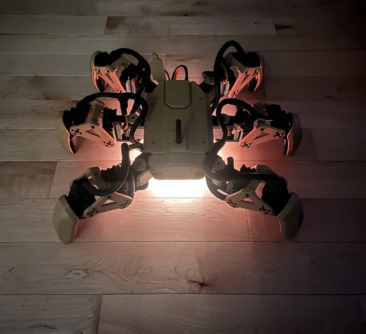
HEX-B12.V120 is a custom designed hexapod using mg996r servos and has it's theme based on the beloved bot B-12 from the popular video game STRAY.
HEX remote is an open-source printed circuit board by Josh4minee, from the Josh4minee/HEX-B12.V1 repository on GitHub, published under the MIT licence. It is a 2-layer board of 107 × 83 mm with 16 parts on 32 nets, routed with 131 tracks and 21 vias.
It is built around the COM-09032. Its parts include 3 switches, 1 resistor and 1 diode. It belongs with the AVR (ATmega, ATtiny) boards of this library.
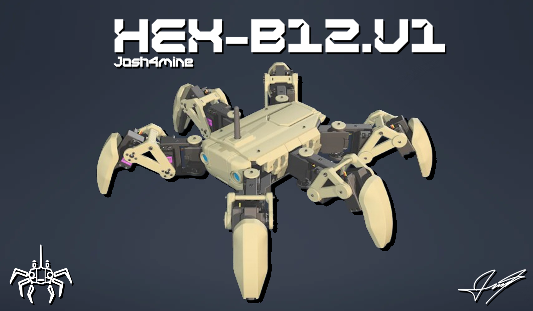
HEX-B12.V120 is a custom-designed hexapod using MG996R servos. Its theme is based on the beloved bot B-12 from the popular video game Stray. It is inspired by the Make Your Pet project and is powered by a custom inverse kinematics-based algorithm.
The mechanical part dimensions are inspired by the Make Your Pet Chipo project; everything else is custom-made by me.
Consult the following based on your needs:
Why I made this hexapod is because since I was young I have always wanted to build "stuff", making robots was always very appealing to me and this project is simpler than a quadruped yet just as fun for a beginner like me and I hope the people that come across this project like it! It is worth mentionning that this is also a college project hense why I have put so much time and effort on it in such a short ammount of time.
As per the title, this hexapod uses MG996R servos, this decision was made because of cost, any other servo is 3x to 4x the price of these ones.
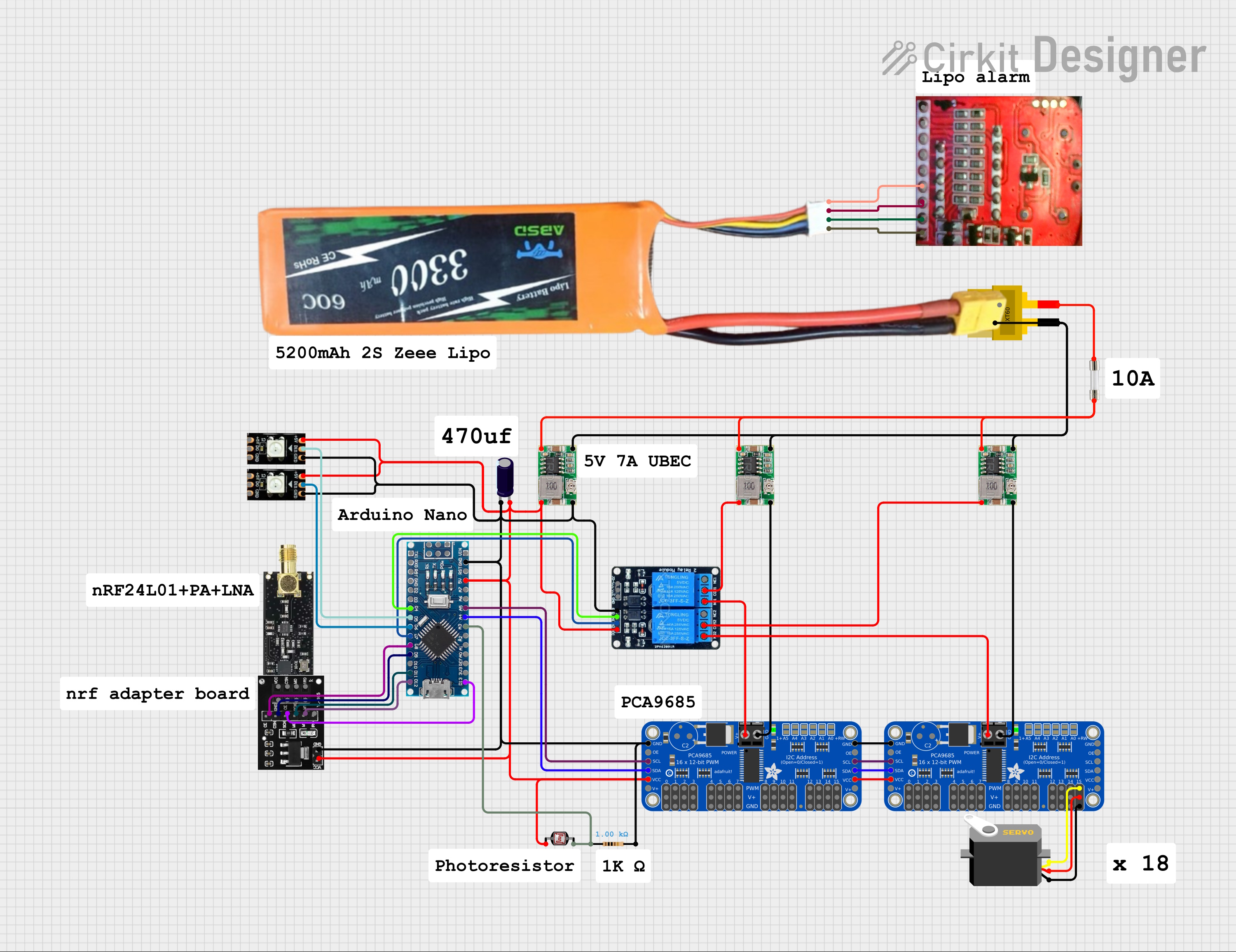
The power system consists of one big 5200mAh 2S lipo battery for optimal opperation time, three UBECs for stable 7v to 5v conversion and one 10A manual reset fuse.
An arduino nano was used as the brains of this project simply because it was a requirement from my college and it is thanfully fast enough for its use case.
An Adafruit PCA9685 servo driver was chosen to controll the huge amount fof servos this robot requires.
The nRF24L01+PA+LNA modules were chosen for wireless communication, the power emplified version was used for its antenna (to keep the resemblance of B-12) and for its range.
Finally, relays were added for ease of use and safety, like only turning on the servos 5s after the battery is pluged in.
The main reason the remote was made is because I did not want to work with bluetooth or web based control.
Making a remote seemed more interesting anyways and it allowed me to design my very first custom PCB:
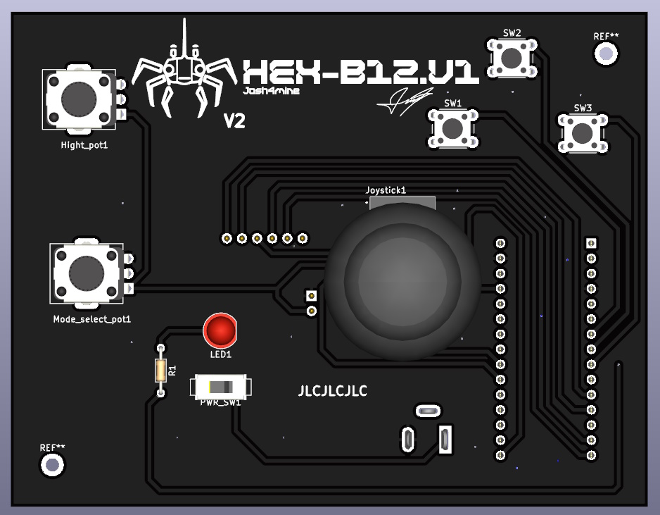
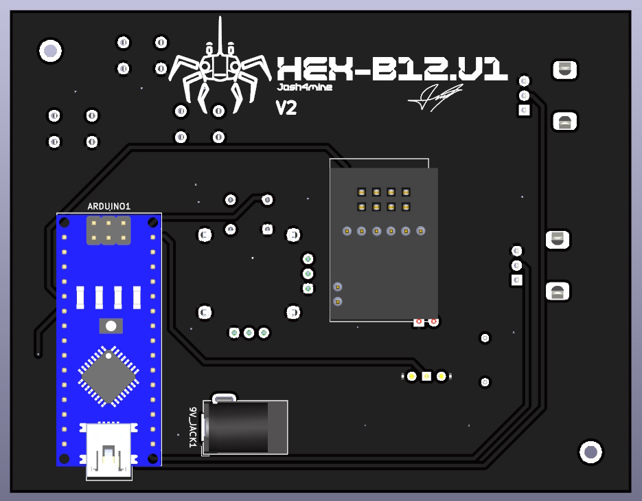
I ended up making 2 versions because I tried to directly hook up an NRF module on the first version, this ended up failing to I just made a custom footprint for the NRF module power boards.
The following are the settings used to print this hexapod:
Here you can find the wiring diagram, component placements, and an IRL example of the completed build.
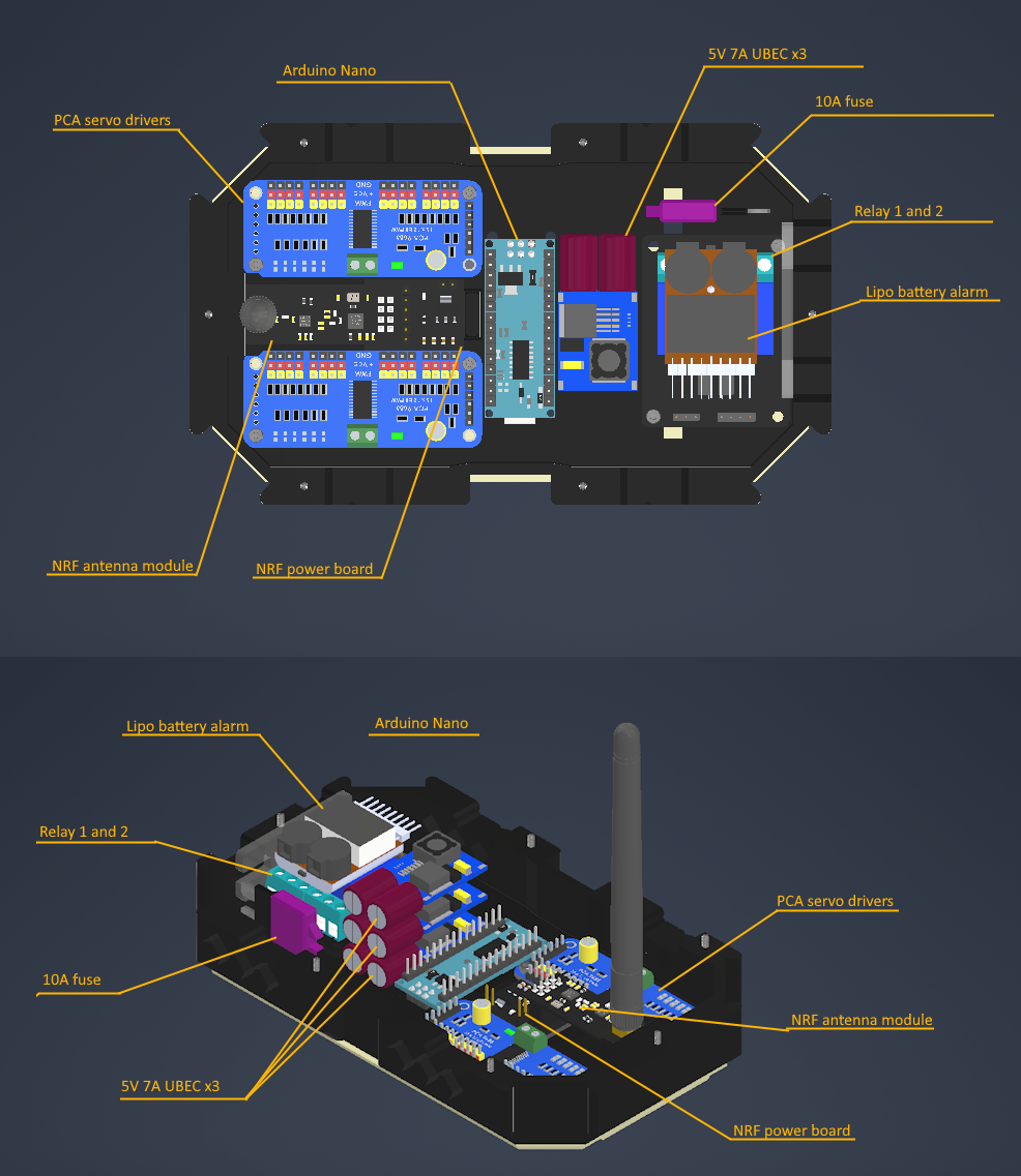
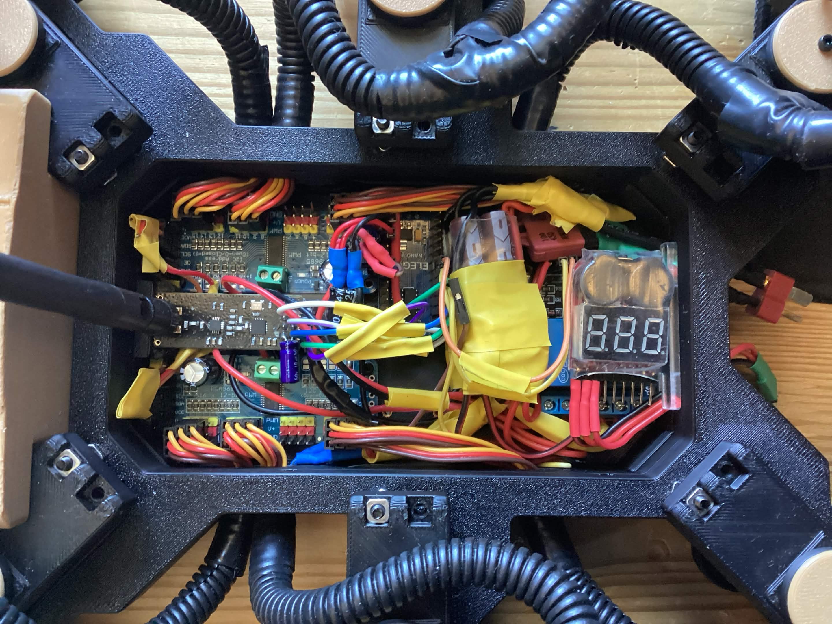
NOTE: ALL SERVOS MUST BE SET TO 90 PRIOR TO ANY ASSEMBLY
NOTE: KEEP IN MIND THAT 3 OF THESE LEGS ARE FLIPPED
NOTE: DO NOT FORGET THE 18 FRICTION CAP RINGS
The above document provides a visual on how parts are assembled, to assemble this in real life you must follow the Frame and Legs and Hexapod technical drawings. The order of operations is very important here, so making sure proper understanding is acquired before continuing is mandatory.
For screw sizes needed:
Follow this technical drawing for proper leg orientation assembly.
It is very recommended to apply sillicone based grease between the friction caps and legs to prevent plastic wear.
Here is what the robot should look like once fully assembled:
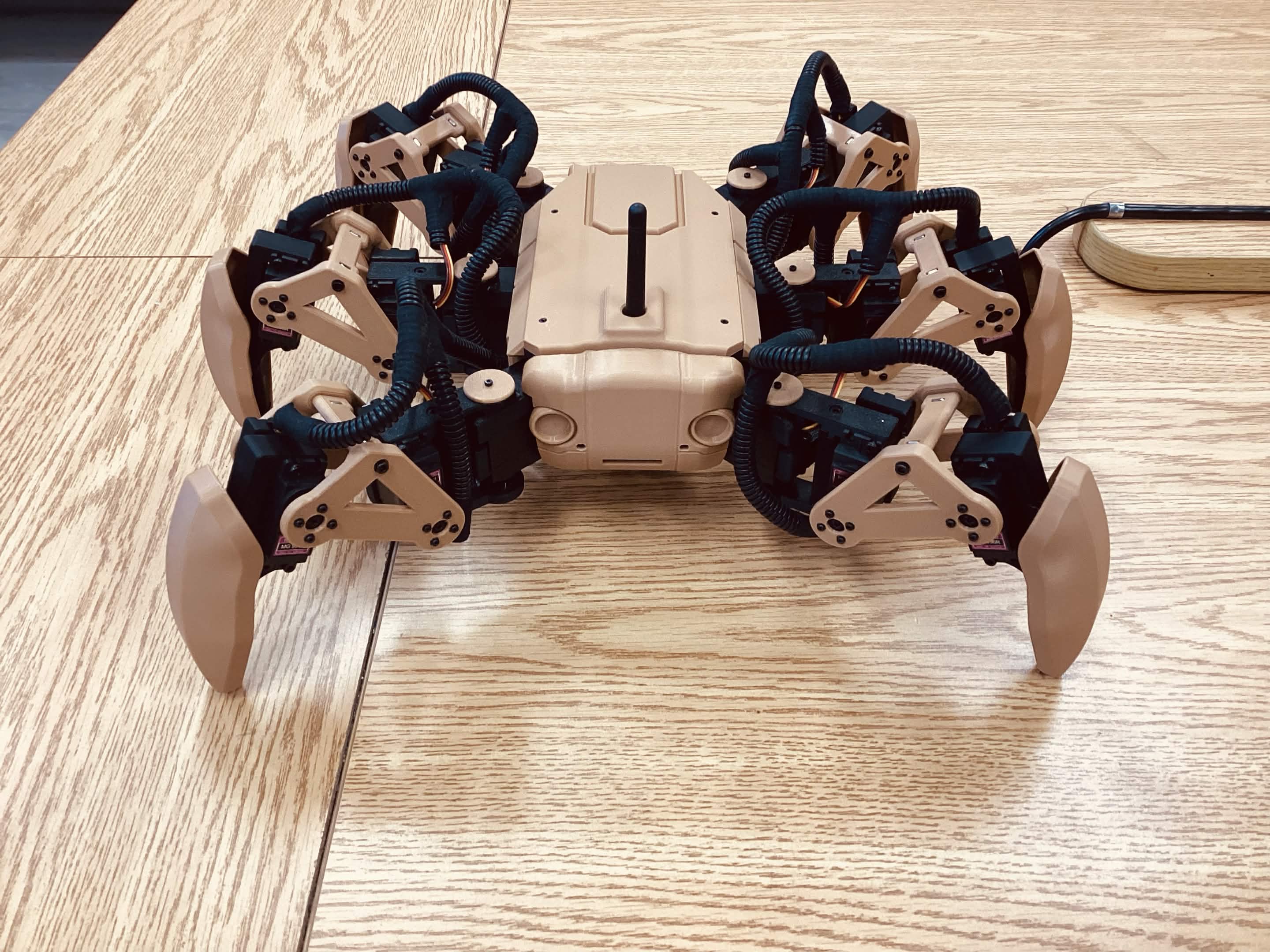
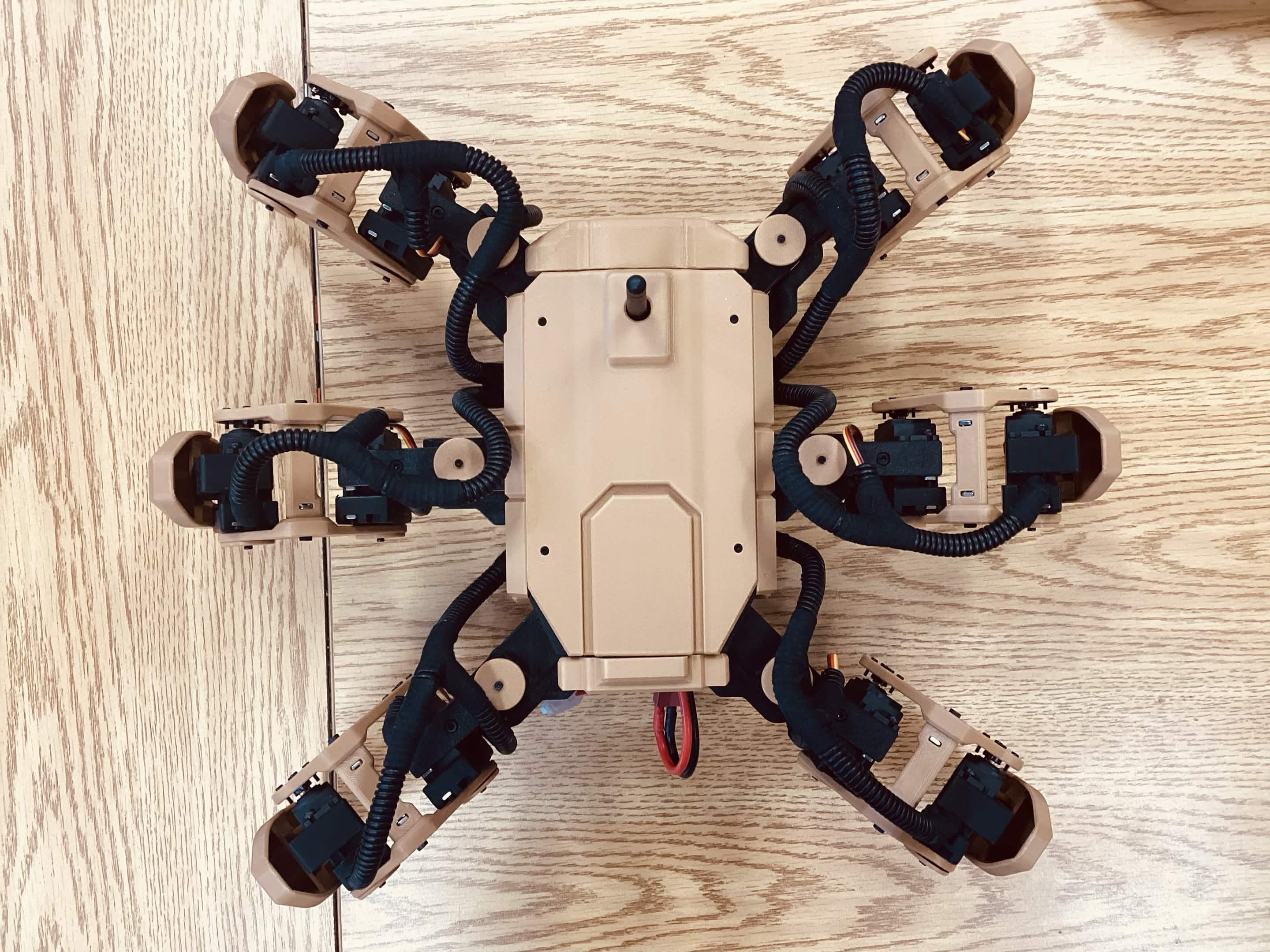
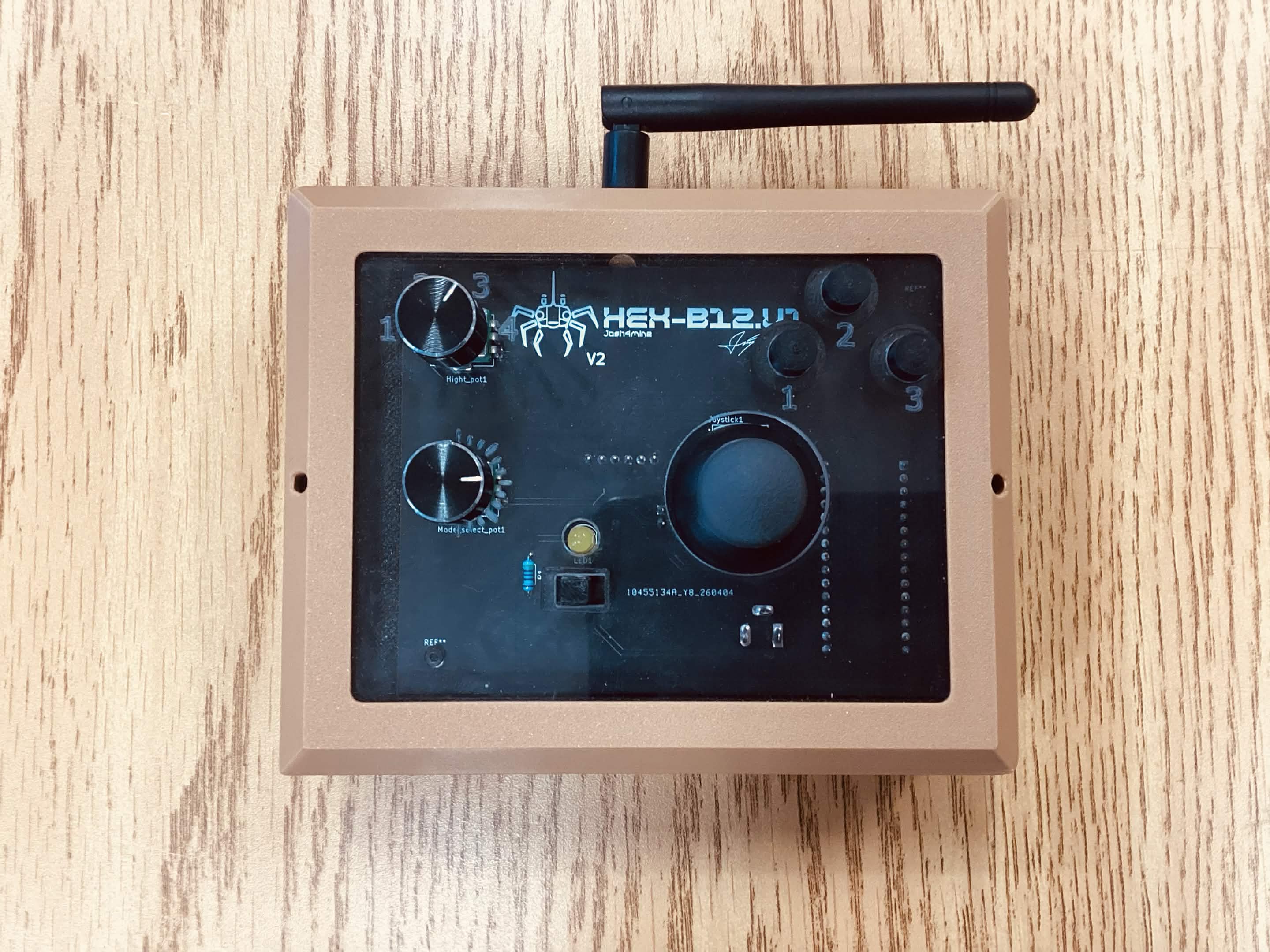
Here is what the remote should look like once fully assembled:
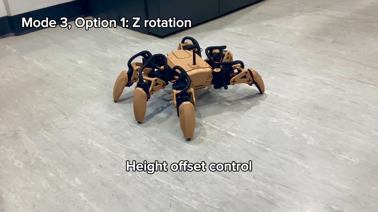
Here is a video demonstrating the functionalities of the hexapod:
Start by buying the PCB on JLCPCB. by simply drag and droping the gerber files.
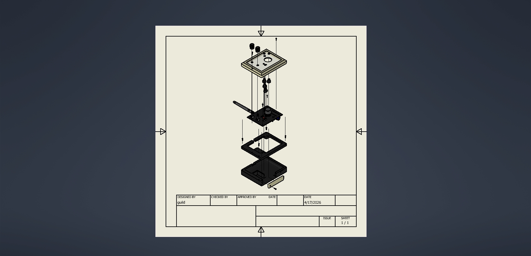
Once you have received and soldered your PCB, follow the diagram to assemble the remote, every screw used is M2 8mm.
The remote has 3 buttons, 2 knobs, and a joystick. The lower knob is for global height offset, the upper knob is used to control which mode the user is in, and the 3 buttons are for 3 different states in these modes:
Normal walking mode: the hexapod turns and follows the joystick’s direction. Each button selects the current walking GAIT: 1 for tripod, 2 for ripple, and 3 is actually an Easter egg.
Crab mode: the hexapod follows joystick directions without ever turning its body. The GAIT selection is the same as above.
Body control mode: here you can control the hexapod body. Button 1 is for planar offset mode, button 2 is for XY rotation offset mode, and button 3 is for Z rotation mode.
Animation mode: in this mode, 3 animations can be selected using the 3 buttons.
Huge thanks to to MYP for the inspiration and just overall help their discord community provided to this project!
Here is a list of every model I used from GrabCad to display electronic components and screws in my assem,blies:
| Qty | Value | Footprint | References |
|---|---|---|---|
| 3 | SW_Push | Button_Switch_THT:SW_PUSH_6mm | SW1, SW2, SW3 |
| 2 | LOGO | COM-09032:MAIN_SPRITE | G***, G*** |
| 2 | R_Potentiometer | Potentiometer_THT:Potentiometer_Alps_RK09K_Single_Vertical | Hight_pot1, Mode_select_pot1 |
| 1 | 330ohm | Resistor_THT:R_Axial_DIN0204_L3.6mm_D1.6mm_P7.62mm_Horizontal | R1 |
| 1 | Arduino_Nano_v3.x | Module:Arduino_Nano | ARDUINO1 |
| 1 | Barrel_Jack | Connector_BarrelJack:BarrelJack_GCT_DCJ200-10-A_Horizontal | 9V_JACK1 |
| 1 | COM-09032 | COM-09032:XDCR_COM-09032 | Joystick1 |
| 1 | LED | LED_THT:LED_D5.0mm | LED1 |
| 1 | SW_SPDT | Button_Switch_THT:SW_Slide-03_Wuerth-WS-SLTV_10x2.5x6.4_P2.54mm | PWR_SW1 |
| 1 | ~ | NRF_ADATOR_FOOTPRINT:NRF_ADAPTER_FOOTPRINT | NRF_port1 |
The 14 most common of 16 parts.
FundamentalFrequency/LMN-3-ECAD
Electrical CAD Files for the LMN-3 Project


Hex-4/glyph
[ a custom split keyboard for portably and comfortably interfacing with computing systems ]

shiva233/Project-Hermes
Project Hermes is a handheld "console" designed for people who already own gaming PCs so they can stream their games via SteamLink so they can take it anywhere for cheap!

kayaked/esp32-ble-mouse-remote
Bluetooth LE hybrid of a computer mouse and a TV remote. (software/electronics)

Reiko0908/NeuralNetwork_Based_AutonomousCar
This project focuses on developing an autonomous car system powered by neural networks (NN). It utilizes deep learning techniques to enable key functionalities such as perception, path planning, and control.

It measures 107 × 83 mm and has 2 copper layers, 1.6 mm thick.
16 parts, built around the COM-09032. The full list of its parts is on this page, with links to each part's symbol and footprint where PCBKit's library has them.
From the Josh4minee/HEX-B12.V1 repository on GitHub, at the commit this page was made from: the board is PCB/HEX_remote.kicad_pcb and its schematic PCB/HEX_remote.kicad_sch. PCBKit opens the board in the browser, with nothing to install.
Its repository publishes it under the MIT licence: you may reuse it on that licence's terms (keep the author's notice, and for a copyleft licence share your changes alike).