


2 layers70 × 20.1 mm
SPD DC MotorHBridge
Jarins/Solder-Paste-Dispenser-with-DCMotor
Motorized solder paste dispenser
48 parts29GPL-3.0
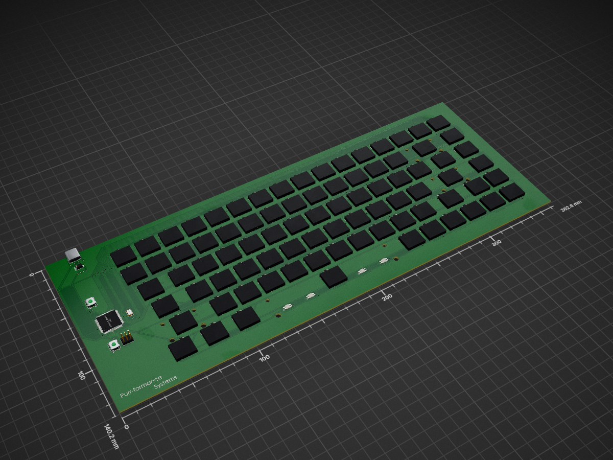
This repository contains all of the PCB related files for the Ambition Keyboard.
Keyboard is an open-source printed circuit board by JosephDemarest, from the JosephDemarest/Ambition_Keyboard_PCB repository on GitHub. It is a 2-layer board of 362.6 × 140.2 mm with 280 parts on 235 nets, routed with 2,260 tracks and 265 vias.
It is built around the AT90USB1286-AU and MBR130LSFT1G-FS. Its parts include 7 capacitors, 6 resistors, 6 switches, 2 connectors and 1 IC. It belongs with the keyboards and input boards and the AVR (ATmega, ATtiny) boards of this library.
This repository contains all of the PCB related files for the Ambition Keyboard. The project is currently in development and is not yet complete.
The keyboard case is currently being designed in CAD. The PCBs have been ordered and are expected to arrive soon. The firmware will be based on QMK.
This repository contains the following:
The firmware for the Ambition Keyboard will be based on QMK. The QMK firmware is a powerful open-source firmware for keyboards that allows for customization and control over every aspect of your keyboard.
To setup the firmware, follow these steps:
git clone https://github.com/qmk/qmk_firmware.gitqmk compile.After building the firmware, you will need to flash it onto your keyboard. Here are the general steps to do this:
Please refer to the QMK documentation for more detailed instructions and troubleshooting tips.
Once the PCBs arrive and have been tested, you will need to solder the components onto the PCB. This includes switches, LEDs, and any other components used in the design.
Once the case design is complete, it will need to be manufactured. The method of manufacturing will depend on the design and materials used. I am planning on 3-d Printing.
As this project is still in development, contributions are welcome. Please feel free to submit issues and pull requests.


| Qty | Value | Footprint | References |
|---|---|---|---|
| 88 | MX_SK6812MINI-E | PCM_marbastlib-mx:LED_MX_6028R | LED_0, LED_1, LED_2, LED_3, LED_4, LED_5, LED_6, LED_7, LED_8, LED_9, LED_A1, LED_B1, LED_BCKSPC1, LED_C1, LED_CAPS1, LED_COLON1 +72 |
| 83 | D | Diode_SMD:D_SOD-123 | D_2, D_10, D_11, D_12, D_13, D_14, D_15, D_16, D_17, D_18, D_19, D_20, D_21, D_22, D_23, D_24 +67 |
| 77 | MX_SW_HS | PCM_marbastlib-mx:SW_MX_HS_1u | MX_0, MX_1, MX_2, MX_3, MX_4, MX_5, MX_6, MX_7, MX_8, MX_9, MX_A1, MX_B1, MX_BKSPC1, MX_C1, MX_COLON1, MXL1 +61 |
| 3 | 100n | Capacitor_SMD:C_0201_0603Metric | C4, C5, C6 |
| 3 | MX_SW_HS | PCM_marbastlib-mx:SW_MX_HS_1.25u | MX_LALT1, MX_LCTRL1, MX_WIN1 |
| 2 | 22pF | Capacitor_SMD:C_01005_0402Metric | C1, C2 |
| 2 | 22r | Resistor_SMD:R_0201_0603Metric | R3, R4 |
| 2 | 5.1k | Resistor_SMD:R_0201_0603Metric | R1, R2 |
| 2 | MX_SW_HS | PCM_marbastlib-mx:SW_MX_HS_1.75u | MX_CAPS1, MX_RSHIFT1 |
| 2 | MX_SW_HS | PCM_marbastlib-mx:SW_MX_HS_1.5u | MX_PIPE1, MX_TAB1 |
| 1 | MBR130LSFT1G | Diode_SMD:D_SMA | D1 |
| 1 | 10k | Resistor_SMD:R_0201_0603Metric | R5 |
| 1 | 10uF | Capacitor_SMD:C_0201_0603Metric | C7 |
| 1 | 16Mhz | Crystal:Crystal_SMD_5032-2Pin_5.0x3.2mm | Y1 |
| 1 | 1k | Resistor_SMD:R_0201_0603Metric | R6 |
| 1 | 1uF | Capacitor_SMD:C_0201_0603Metric | C3 |
| 1 | AT90USB1286-A | Package_QFP:TQFP-64_14x14mm_P0.8mm | U1 |
| 1 | D_Small | Diode_SMD:D_SOD-123 | D_1 |
| 1 | HWB | Button_Switch_SMD:SW_SPST_B3SL-1002P | SW2 |
| 1 | ISP | Connector_PinHeader_2.54mm:PinHeader_2x03_P2.54mm_Vertical | CON1 |
| 1 | MX_stab_BKSPC | PCM_marbastlib-mx:STAB_MX_2u | S1 |
| 1 | MX_stab_ENTER | PCM_marbastlib-mx:STAB_MX_2.25u | S2 |
| 1 | MX_stab_LSHIFT | PCM_marbastlib-mx:STAB_MX_2.25u | S3 |
| 1 | MX_stab_SPACE | PCM_marbastlib-mx:STAB_MX_6.25u | S4 |
| 1 | RESET | Button_Switch_SMD:SW_SPST_B3SL-1002P | SW1 |
| 1 | USB_C_Receptacle_USB2.0 | Connector_USB:USB_C_Receptacle_GCT_USB4085 | J1 |
Jarins/Solder-Paste-Dispenser-with-DCMotor
Motorized solder paste dispenser

digitalrane/ec0board
QMK AT90USB1286 Mechanical TKL Keyboard - Retrofit for Kogan Mechanical TKL

Jarins/STM32F407-RAMPS
RAMPS for STM32F407ZE_ZG Dev. Board Black edition

afewyards/HydroMix
A mains-powered, Zigbee-connected controller for a hydronic 3-way mixing valve — it regulates the supply-water temperature of a floor heating/cooling system and keeps regulating autonomously if the Zigbee link goes down.

johnktaylor/protoworks-kicad-3-3v-regulator
A 3.3v Regulator and USB-C breakout board licensed under CERN-OHL-W-2.0

MaxClerkwell/kicad-workshop
KiCon 2026 workshop: KiCad 10 Professional Workflows — staged course files for the Acme USB Hub design


It measures 362.6 × 140.2 mm and has 2 copper layers, 1.6 mm thick.
280 parts, built around the AT90USB1286-AU and MBR130LSFT1G-FS. The full list of its parts is on this page, with links to each part's symbol and footprint where PCBKit's library has them.
From the JosephDemarest/Ambition_Keyboard_PCB repository on GitHub, at the commit this page was made from: the board is keyboard.kicad_pcb and its schematic keyboard.kicad_sch. PCBKit opens the board in the browser, with nothing to install.
Its repository states no licence, so its author keeps all rights: ask JosephDemarest before reusing the design.