2 layers23.4 × 27 mm

 JorisBar/Simon_pocket1
A pocket version of the classic Simon says game
Simon pocket panel is an open-source printed circuit board by JorisBar, from the JorisBar/Simon_pocket repository on GitHub. It is a 2-layer board of 85.4 × 102.1 mm with 378 parts on 52 nets, routed with 2,070 tracks and 261 vias.
Its parts include 117 resistors, 90 capacitors, 36 diodes, 36 connectors and 36 switches. It belongs with the STM32 boards of this library.
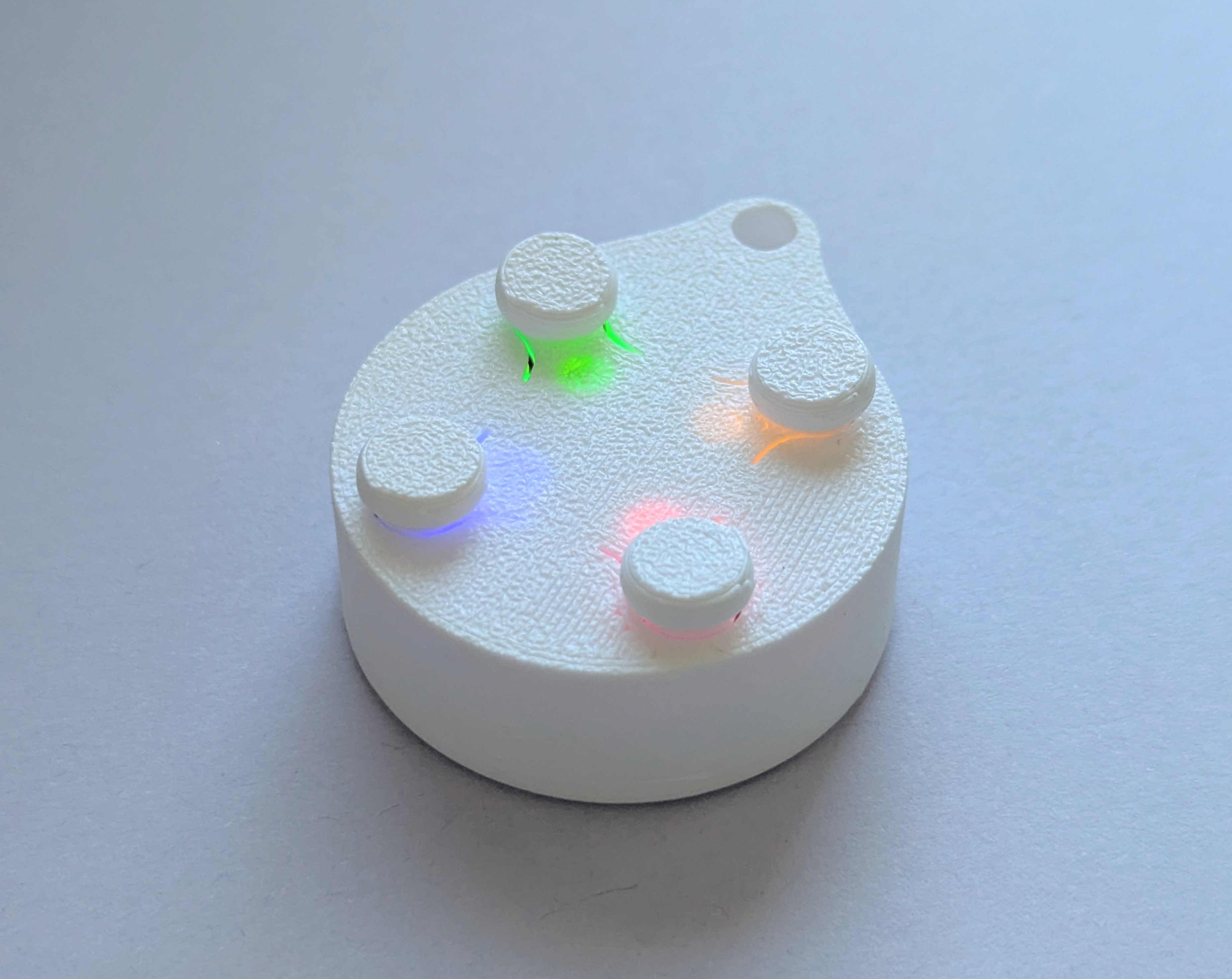
Simon_pocket is a pocket sized memory training game. Players have to repeat a button sequence that gets longer each round. This project includes a custom PCB, bare metal programming for an STM32 MCU and a 3D printed housing.


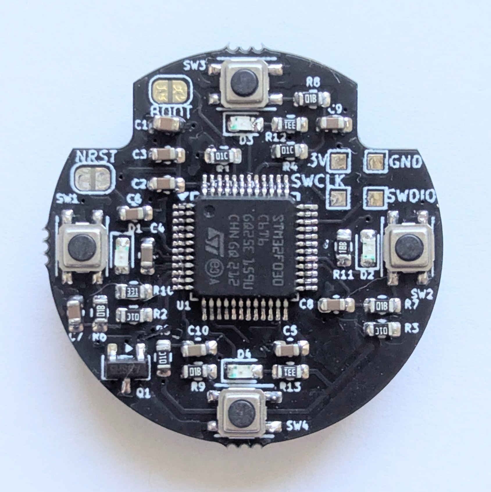
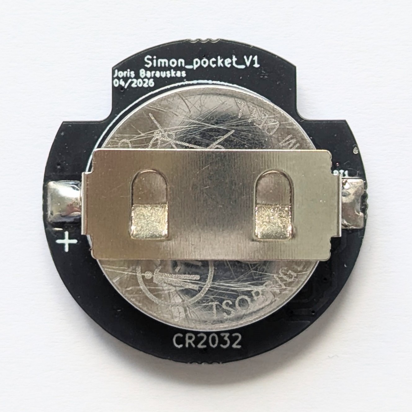
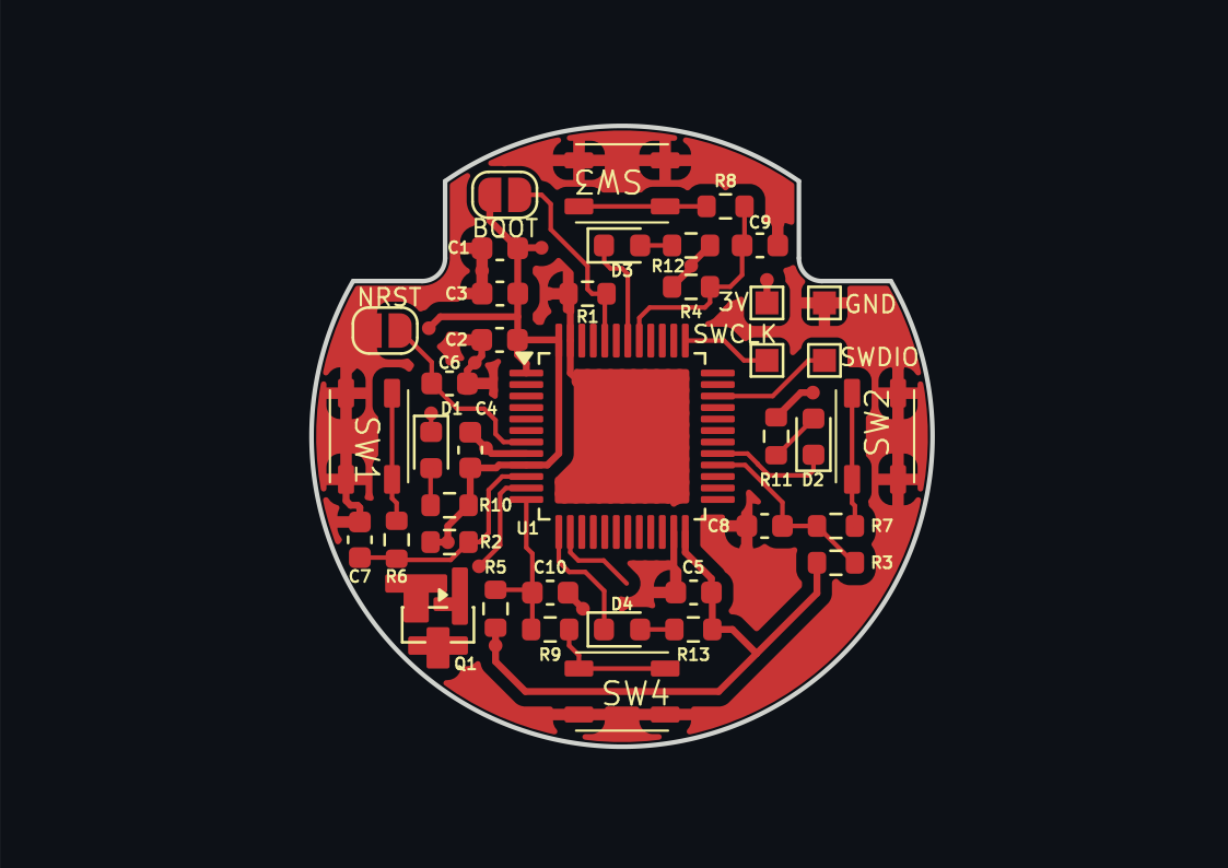
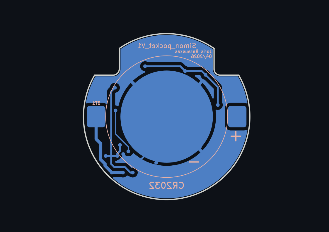
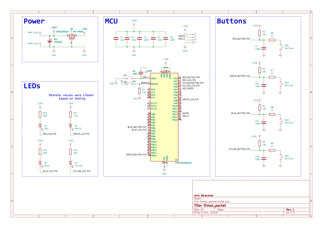
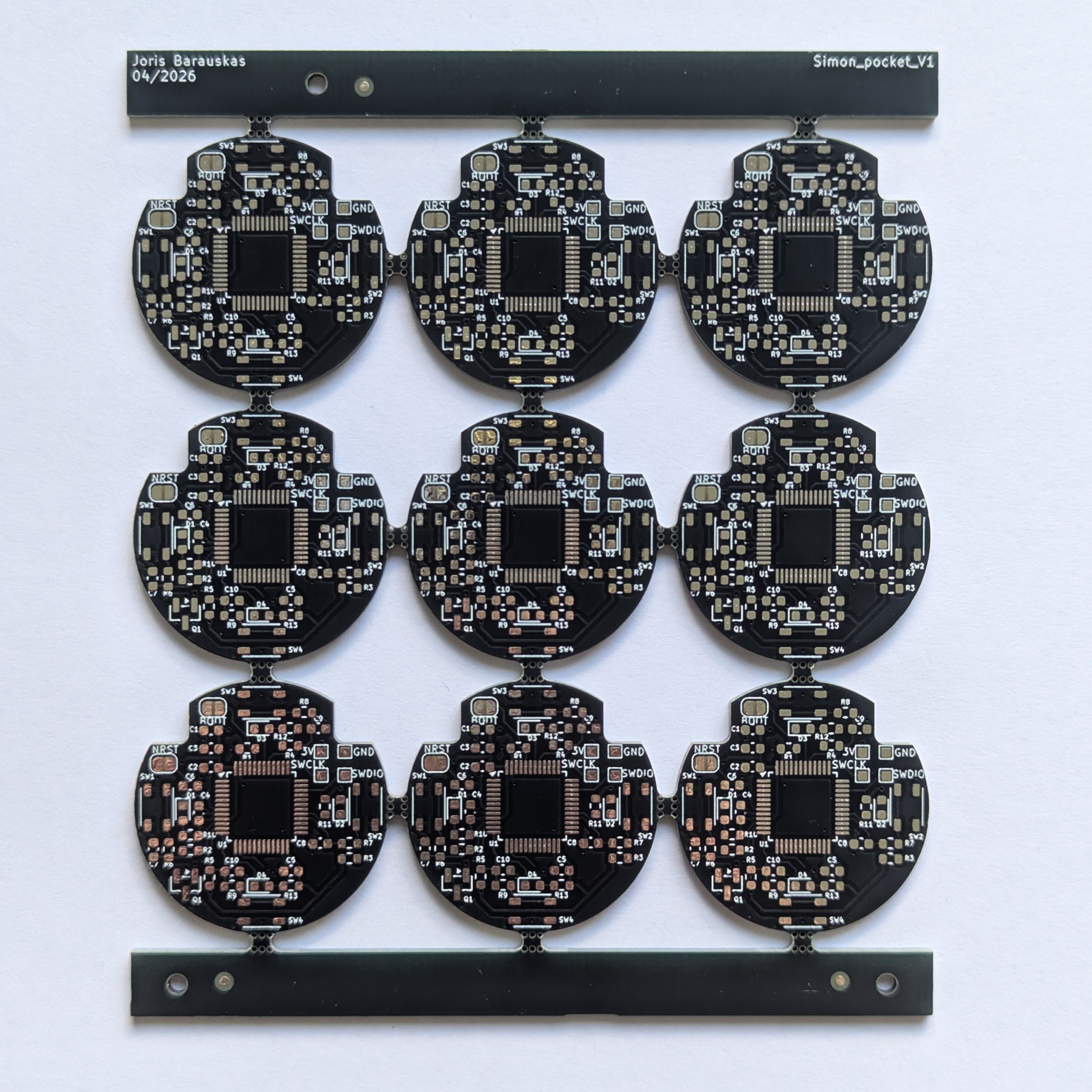
A PCB panel was designed to decrease the cost of each PCB.
The code was written in bare metal CMSIS C using the STM32CubeIDE. To upload the code an ST-LINK V2 has to be connected to the programming contacts on the PCB.


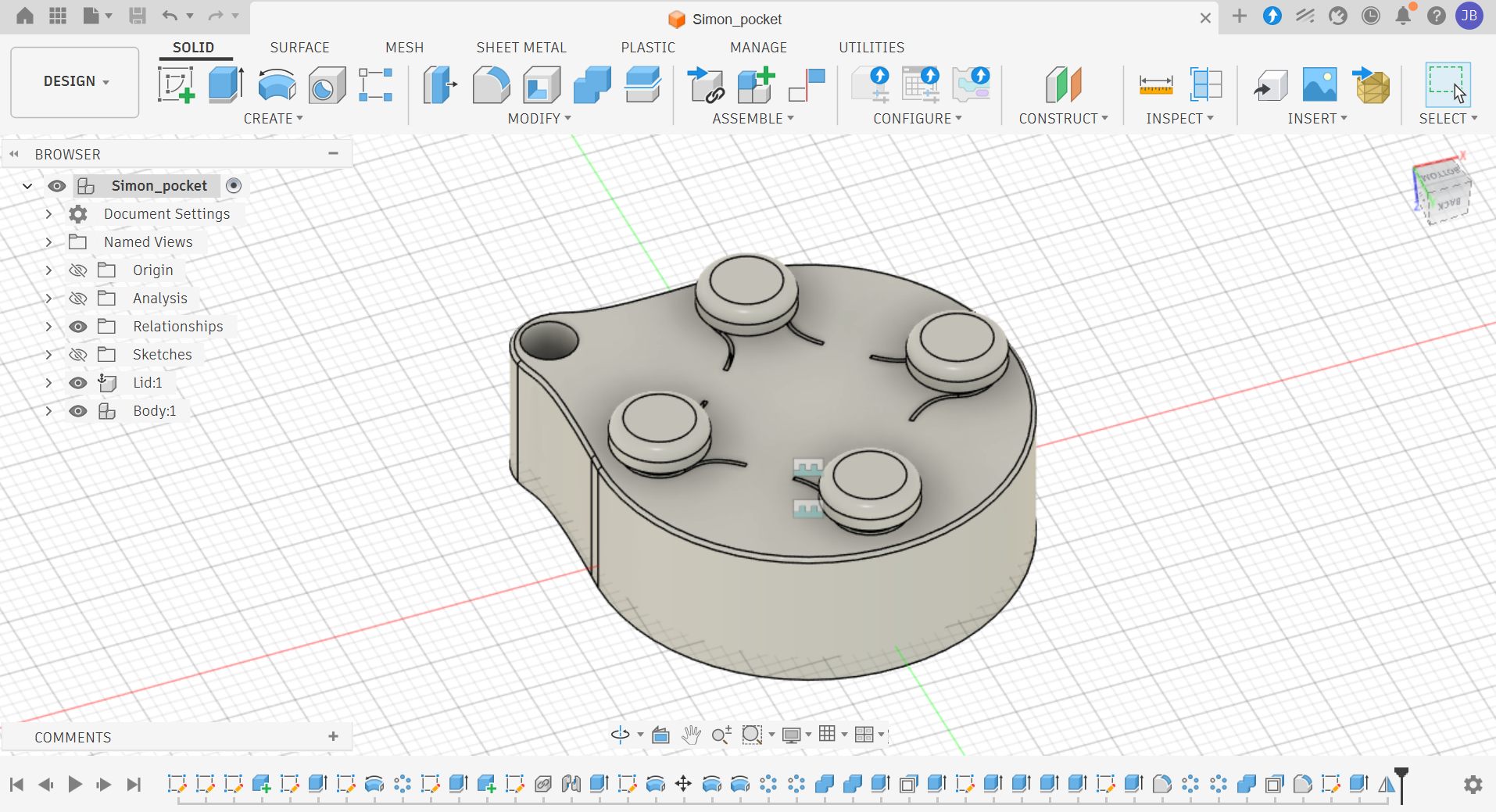
The housing was modeled using Autodesk Fusion. It was printed using a Bambu Lab A1 mini 3D printer.
| Qty | Value | Footprint | References |
|---|---|---|---|
| 81 | 100n | Capacitor_SMD:C_0603_1608Metric | C2, C2, C2, C2, C2, C2, C2, C10, C10, C10, C10, C10, C10, C10, C10, C10 +65 |
| 45 | 10k | Resistor_SMD:R_0603_1608Metric | R1, R1, R1, R1, R1, R1, R1, R1, R1, R2, R2, R2, R2, R2, R2, R2 +29 |
| 36 | 1k | Resistor_SMD:R_0603_1608Metric | R6, R6, R6, R6, R6, R6, R6, R6, R6, R7, R7, R7, R7, R7, R7, R7 +20 |
| 36 | Conn_01x01_Pin | TestPoint:TestPoint_Pad_1.0x1.0mm | J1, J1, J1, J1, J1, J1, J1, J1, J1, J2, J2, J2, J2, J2, J2, J2 +20 |
| 36 | SW_Push | My library:SW_Push mini square | SW1, SW1, SW1, SW1, SW1, SW1, SW1, SW1, SW1, SW2, SW2, SW2, SW2, SW2, SW2, SW2 +20 |
| 27 | 330 | Resistor_SMD:R_0603_1608Metric | R10, R10, R10, R10, R10, R10, R10, R10, R10, R12, R12, R12, R12, R12, R12, R12 +11 |
| 18 | Jumper_2_Open | Jumper:SolderJumper-2_P1.3mm_Open_RoundedPad1.0x1.5mm | JP1, JP1, JP1, JP1, JP1, JP1, JP1, JP1, JP1, JP2, JP2, JP2, JP2, JP2, JP2, JP2 +2 |
| 9 | 1.5k | Resistor_SMD:R_0603_1608Metric | R11, R11, R11, R11, R11, R11, R11, R11, R11 |
| 9 | 10u | Capacitor_SMD:C_0603_1608Metric | C1, C1, C1, C1, C1, C1, C1, C1, C1 |
| 9 | BLUE | LED_SMD:LED_0603_1608Metric | D3, D3, D3, D3, D3, D3, D3, D3, D3 |
| 9 | Battery_Cell | My library:CR2032 slim holder | BT1, BT1, BT1, BT1, BT1, BT1, BT1, BT1, BT1 |
| 9 | GREEN | LED_SMD:LED_0603_1608Metric | D2, D2, D2, D2, D2, D2, D2, D2, D2 |
| 9 | PMOS | Package_TO_SOT_SMD:SOT-23 | Q1, Q1, Q1, Q1, Q1, Q1, Q1, Q1, Q1 |
| 9 | RED | LED_SMD:LED_0603_1608Metric | D1, D1, D1, D1, D1, D1, D1, D1, D1 |
| 9 | STM32F030C6Tx | Package_QFP:LQFP-48_7x7mm_P0.5mm | U1, U1, U1, U1, U1, U1, U1, U1, U1 |
| 9 | YELLOW | LED_SMD:LED_0603_1608Metric | D4, D4, D4, D4, D4, D4, D4, D4, D4 |
The 360 most common of 378 parts.


akita11/USBCpow
以下、3.3V出力を作る場合の追加部品 - レギュレータLM1117-3.3(または互換品) 1個 - チップコンデンサ 10uF(1608サイズ)/10V以上 2個 ※C1,C2のところに実装


wonzaj/Amplituner
Audio amplituner with display, bass, middle, treble control. It has:


Julesc013/project-carbon
Hardware and software for custom CPUs, FPUs, and computer systems.
It measures 85.4 × 102.1 mm and has 2 copper layers, 1.6 mm thick.
378 parts. The full list of its parts is on this page, with links to each part's symbol and footprint where PCBKit's library has them.
From the JorisBar/Simon_pocket repository on GitHub, at the commit this page was made from: the board is PCB/Panel/Simon_pocket_panel.kicad_pcb and its schematic PCB/Standard/Simon_pocket.kicad_sch. PCBKit opens the board in the browser, with nothing to install.
Its repository states no licence, so its author keeps all rights: ask JorisBar before reusing the design.