
2 layers60 × 100 mm

 JorianZwerver/HeatingBoard2
Heating Board PCB for module 11 for BSc EE
HeatingBoard is an open-source printed circuit board by JorianZwerver, from the JorianZwerver/HeatingBoard repository on GitHub. It is a 2-layer board of 80 × 60 mm with 108 parts on 53 nets, routed with 425 tracks and 154 vias.
It is built around the DMP3099L and T2N7002AK,LM. Its parts include 46 resistors, 14 capacitors, 13 ICs, 5 connectors and 4 fuses.
PCB for MOD11 project. Measures current of four channels and can PWM each channel using a PMOS circuit.
Schematic: Schematic
Test results: Results
Test code for Arduino Uno: Code
The board has 5 connectors:
| Connector ID | Description |
|---|---|
| J1 | Battery connector, is used for power. |
| J2 | Input interface for control, has a PWM pin for each group and the input for the 3V3 power. |
| J3 | I2C connector, contains SDA, SCL and GND. However, the GND pin is broken and does not work. |
| J4 | I2C connector, contains SDA, SCL and GND. |
| J5 | Output to the heating sleeve. Has four outputs and a GND that power the sleeve. |
The current sensors communicate over the I2C bus. They need 3V3 power, but not battery power. The addresses are stated below:
| Channel number | Address (HEX) | Address (BIN) | Shunt resistor value (mOhm) |
|---|---|---|---|
| 1 | 0x45 | 1000101 | 101 |
| 2 | 0x44 | 1000100 | 101.2 |
| 3 | 0x41 | 1000001 | 100.5 |
| 4 | 0x40 | 1000000 | 100.6 |
The datasheet can be found using this link. We have tested the current sensors in combination with a small load and encountered problems with the PWM, since the current sensor would sometimes measure the full current and sometimes zero current. To solve this, we increased the sample size and PWM frequency. This does mean that the sensor takes ~ 70 ms to get new data. We recommend the following settings:
We have found pretty accurate results using these settings, only deviating a couple of mW from the power supply. The testing code can be found here. The resistor values of the current shunts are shown in the table with the addresses for the current sensors.
During testing, we found that the duty cycle of the output voltage starts deviating from the input duty cycle for higher PWM frequencies. We have tested this for frequencies of 2.5, 5 and 10 kHz and we recommend 2.5 kHz. All results can be found in the test report.
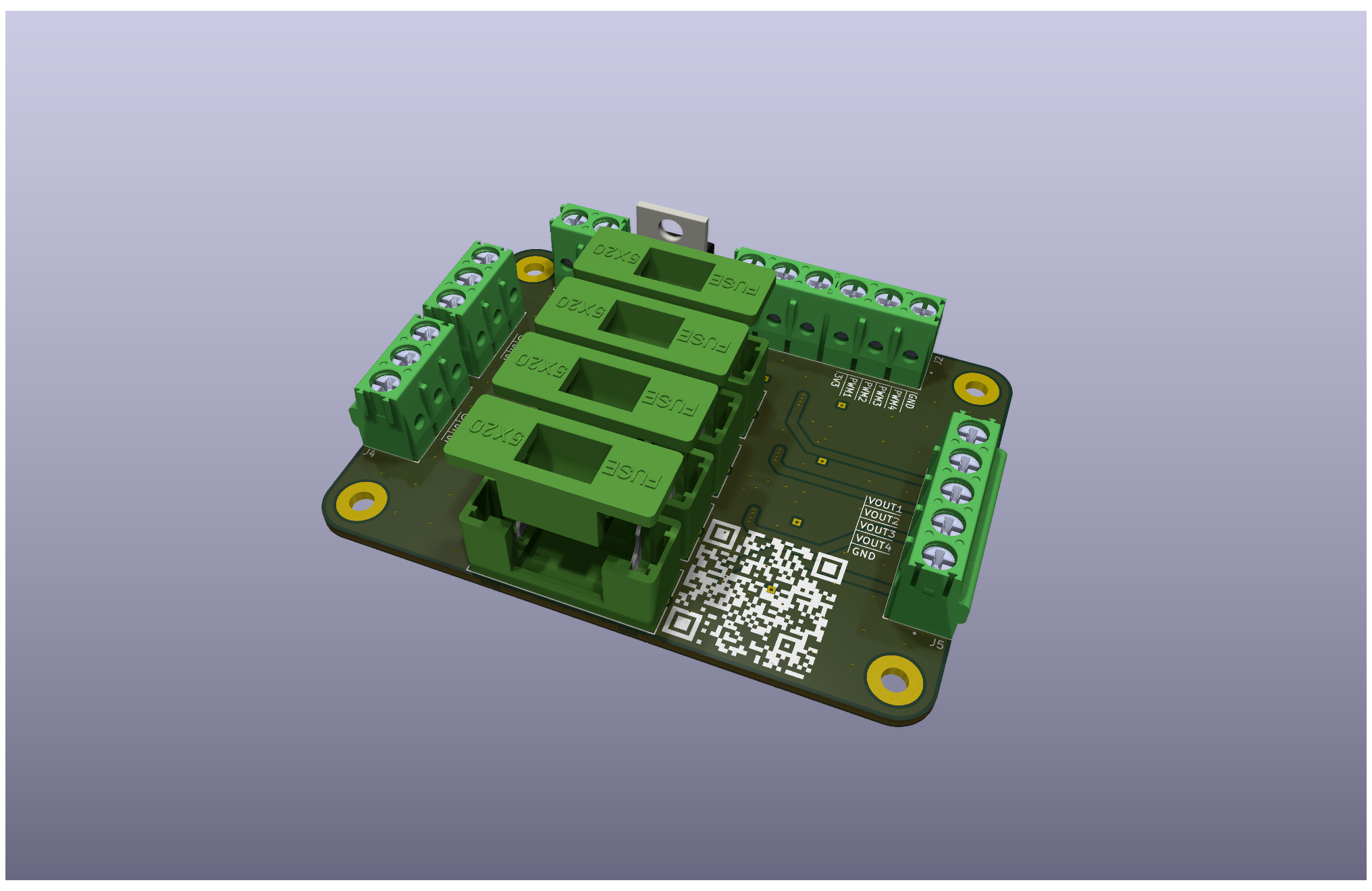
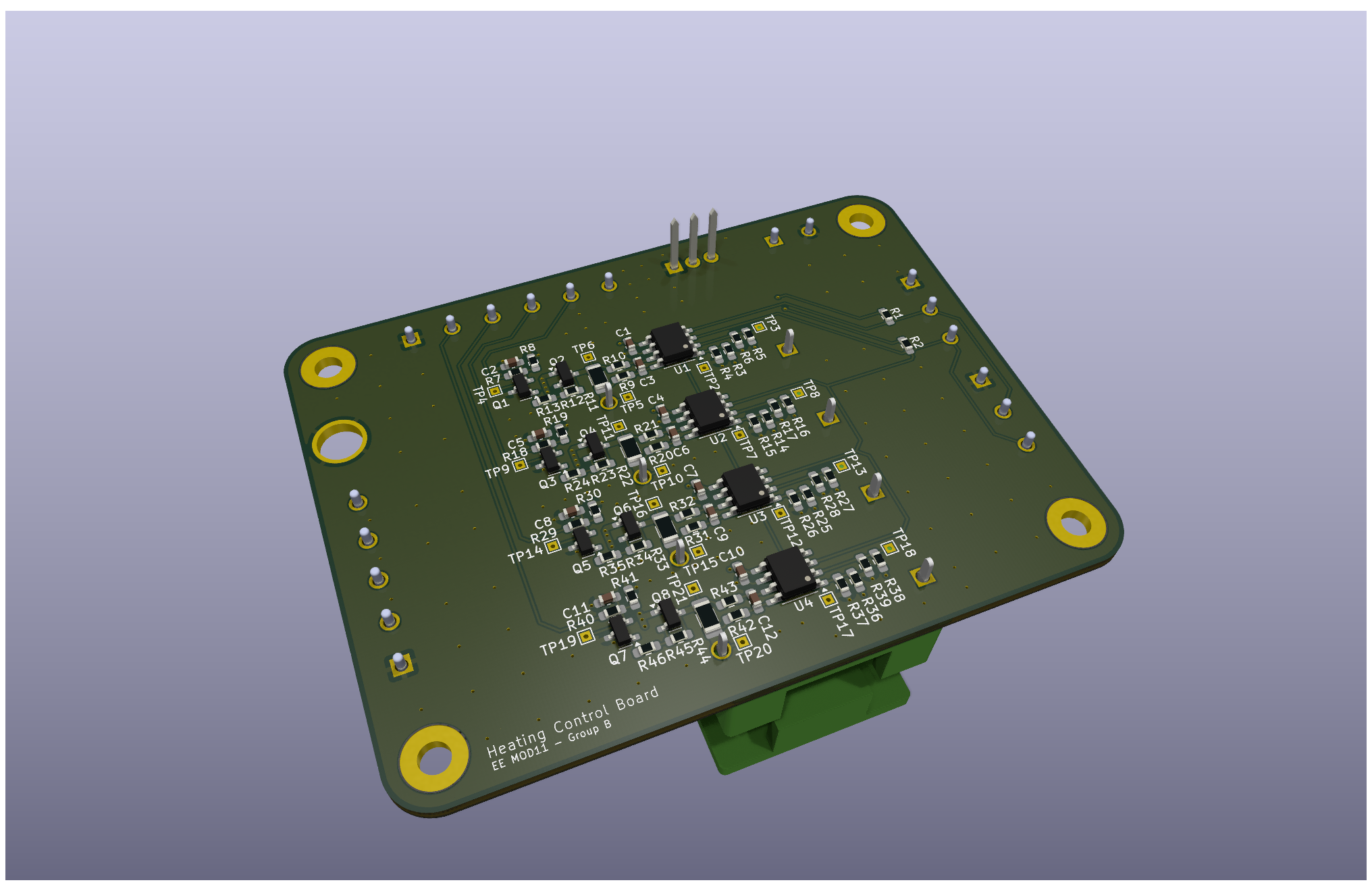
| Qty | Value | Footprint | References |
|---|---|---|---|
| 20 | 10k | Resistor_SMD:R_0603_1608Metric_Pad0.98x0.95mm_HandSolder | R4, R12, R13, R15, R17, R19, R23, R24, R26, R28, R30, R34, R35, R37, R39, R41 +4 |
| 20 | TestPoint | TestPoint:TestPoint_THTPad_1.0x1.0mm_Drill0.5mm | TP2, TP3, TP4, TP5, TP10, TP11, TP12, TP13, TP14, TP15, TP16, TP17, TP18, TP19, TP20, TP21 +4 |
| 12 | 0R | Resistor_SMD:R_0603_1608Metric_Pad0.98x0.95mm_HandSolder | R7, R9, R10, R18, R20, R21, R29, R31, R32, R40, R42, R43 |
| 8 | DNP | Resistor_SMD:R_0603_1608Metric_Pad0.98x0.95mm_HandSolder | R3, R5, R14, R16, R25, R27, R36, R38 |
| 8 | DNP | Capacitor_SMD:C_0603_1608Metric_Pad1.08x0.95mm_HandSolder | C2, C3, C5, C6, C8, C9, C11, C12 |
| 4 | 0.1R | Resistor_SMD:R_1206_3216Metric_Pad1.30x1.75mm_HandSolder | R11, R22, R33, R44 |
| 4 | 100n | Capacitor_SMD:C_0603_1608Metric_Pad1.08x0.95mm_HandSolder | C1, C4, C7, C10 |
| 4 | 3A fuse | HeatingBoard:FUSE_0PTF0078P_LTF | F1, F2, F3, F4 |
| 4 | DMP3099L | Package_TO_SOT_SMD:SOT-23 | U6, U7, U8, U9 |
| 4 | INA219BxD | Package_SO:SOIC-8_3.9x4.9mm_P1.27mm | U1, U2, U3, U4 |
| 4 | MountingHole_Pad | MountingHole:MountingHole_3.2mm_M3_Pad | H1, H2, H3, H4 |
| 4 | T2N7002AK,LM | Package_TO_SOT_SMD:SOT-23 | U10, U11, U12, U13 |
| 2 | 10u | Capacitor_SMD:C_0805_2012Metric_Pad1.18x1.45mm_HandSolder | C13, C14 |
| 2 | 2k2 | Resistor_SMD:R_0603_1608Metric_Pad0.98x0.95mm_HandSolder | R1, R2 |
| 2 | Conn_01x03 | HeatingBoard:PHOENIX_1935174 | J3, J4 |
| 1 | AZ1117-3.3 | Package_TO_SOT_THT:TO-220-3_Vertical | U5 |
| 1 | Conn_01x02 | HeatingBoard:PHOENIX_1935161 | J1 |
| 1 | Conn_01x05 | HeatingBoard:PHOENIX_1935190 | J5 |
| 1 | Conn_01x06 | HeatingBoard:PHOENIX_1935200 | J2 |
| 1 | QR code | HeatingBoard:QRcode | H5 |
| 1 | TestPoint | TestPoint:TestPoint_Plated_Hole_D5.0mm | TP1 |


introlab/t-top
T-Top is a tabletop robot designed with advanced audio and vision sensors, deep learning perceptual processing and telecommunication capabilities to provide richer interaction modalities and develop higher cognitive…

hackclub/thing
Many Hack Clubbers will add a tool or something to the same PCB consecutively, and at the end I'll get \10 made and send them off to some people you may or may not have seen on YouTube...


A-Neal/dmx-led-bar-v1
An FPGA-based 6-channel DMX decoder and LED fixture.

It measures 80 × 60 mm and has 2 copper layers, 1.6 mm thick.
108 parts, built around the DMP3099L and T2N7002AK,LM. The full list of its parts is on this page, with links to each part's symbol and footprint where PCBKit's library has them.
From the JorianZwerver/HeatingBoard repository on GitHub, at the commit this page was made from: the board is HeatingBoard.kicad_pcb and its schematic Channel.kicad_sch. PCBKit opens the board in the browser, with nothing to install.
Its repository states no licence, so its author keeps all rights: ask JorianZwerver before reusing the design.