2 layers86 × 58.9 mm

 JordanAceto/CEM3340_VCO4
PCB for a CEM3340 based VCO with sine, triangle, saw, and pulse waves.
CEM3340 VCO is an open-source printed circuit board by JordanAceto, from the JordanAceto/CEM3340_VCO repository on GitHub, published under the CC-BY-4.0 licence. It is a 2-layer board of 55.9 × 78.7 mm with 96 parts on 67 nets, routed with 497 tracks and 92 vias.
It is built around the TL072, MC7905CT and REF02AU, with the MMDT3904 among its other parts. Its parts include 44 resistors, 25 capacitors, 7 ICs, 7 connectors and 1 transistor.


This design does not use the built in CEM3340 pulse generator. Instead, an typical opamp circuit is used for the Pulse wave output. This is to avoid the influence of PWM on the frequency of the oscillator, which has been reported to be a problem, especially with the AS3340 versions of the chip. The built in pulse generator is disabled by tying the output to ground through a resistor, and hardwiring a negative voltage into pin 5 which permanently sets the pulse width to zero percent.
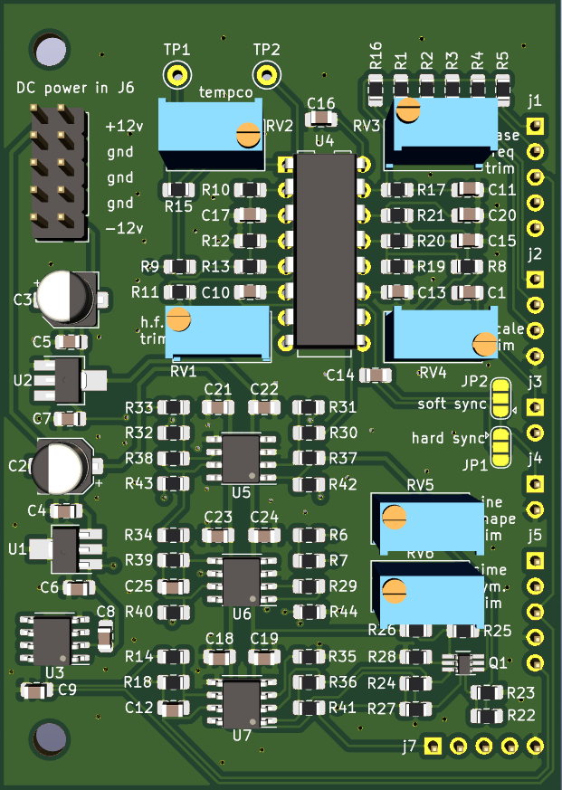
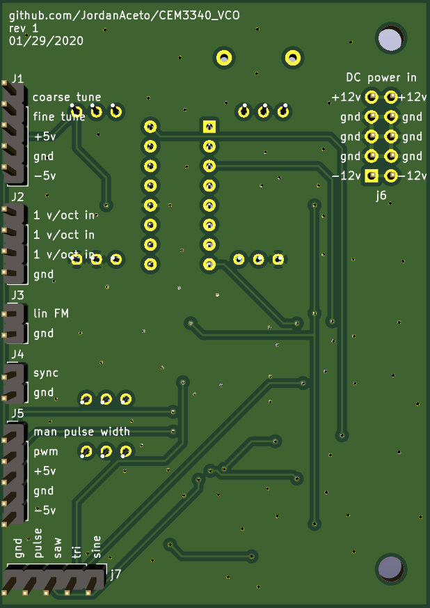
| Revision | breadboarded | schematic | pcb layout | built and tested | documentation |
|---|---|---|---|---|---|
| 1 | ☑ | ☑ | ☑ | ☑ | ☑ |
I've built three of these, and they work well and are fairly easy to build. The dual NPN in the sine shaper is a little small, but after doing a few of them I can solder them reliably without any grief.
Calibration is pretty straightforward and they tune up nicely and don't drift badly with changes in temperature. I have not done any rigorous testing, just by-ear, but I'm pretty picky about out of tune VCOs and these seem good to me so far.
Overall quite happy with this VCO.
| Qty | Value | Footprint | References |
|---|---|---|---|
| 16 | 100nF | Capacitor_SMD:C_0805_2012Metric_Pad1.15x1.40mm_HandSolder | C1, C4, C5, C6, C7, C8, C9, C12, C16, C17, C18, C19, C21, C22, C23, C24 |
| 10 | 100k | Resistor_SMD:R_0805_2012Metric_Pad1.15x1.40mm_HandSolder | R1, R2, R3, R5, R7, R29, R31, R33, R37, R38 |
| 5 | 10k | Resistor_SMD:R_0805_2012Metric_Pad1.15x1.40mm_HandSolder | R14, R18, R24, R27, R34 |
| 3 | 1M | Resistor_SMD:R_0805_2012Metric_Pad1.15x1.40mm_HandSolder | R4, R8, R11 |
| 3 | 1k | Resistor_SMD:R_0805_2012Metric_Pad1.15x1.40mm_HandSolder | R41, R42, R43 |
| 3 | 1nF | Capacitor_SMD:C_0805_2012Metric_Pad1.15x1.40mm_HandSolder | C10, C13, C14 |
| 3 | 50k | Potentiometer_THT:Potentiometer_Bourns_3296W_Vertical | RV3, RV5, RV6 |
| 3 | TL072 | Package_SO:SOIC-8_3.9x4.9mm_P1.27mm | U5, U6, U7 |
| 2 | 10nF | Capacitor_SMD:C_0805_2012Metric_Pad1.15x1.40mm_HandSolder | C11, C15 |
| 2 | 10uF | Capacitor_SMD:CP_Elec_5x5.4 | C2, C3 |
| 2 | 15k | Resistor_SMD:R_0805_2012Metric_Pad1.15x1.40mm_HandSolder | R35, R36 |
| 2 | 18k | Resistor_SMD:R_0805_2012Metric_Pad1.15x1.40mm_HandSolder | R15, R26 |
| 2 | 2k | Resistor_SMD:R_0805_2012Metric_Pad1.15x1.40mm_HandSolder | R40, R44 |
| 2 | 2k2 | Resistor_SMD:R_0805_2012Metric_Pad1.15x1.40mm_HandSolder | R23, R28 |
| 2 | 470 | Resistor_SMD:R_0805_2012Metric_Pad1.15x1.40mm_HandSolder | R17, R20 |
| 2 | 51k | Resistor_SMD:R_0805_2012Metric_Pad1.15x1.40mm_HandSolder | R12, R13 |
| 2 | 5k6 | Resistor_SMD:R_0805_2012Metric_Pad1.15x1.40mm_HandSolder | R9, R10 |
| 2 | MountingHole | MountingHole:MountingHole_3.2mm_M3 | H1, H2 |
| 2 | TestPoint | TestPoint:TestPoint_Keystone_5000-5004_Miniature | TP1, TP2 |
| 1 | 1 v/oct inputs | Connector_PinHeader_2.54mm:PinHeader_1x04_P2.54mm_Vertical | J2 |
| 1 | 10M | Resistor_SMD:R_0805_2012Metric_Pad1.15x1.40mm_HandSolder | R39 |
| 1 | 10pF | Capacitor_SMD:C_0805_2012Metric_Pad1.15x1.40mm_HandSolder | C25 |
| 1 | 110k | Resistor_SMD:R_0805_2012Metric_Pad1.15x1.40mm_HandSolder | R6 |
| 1 | 1k62 | Resistor_SMD:R_0805_2012Metric_Pad1.15x1.40mm_HandSolder | R21 |
| 1 | 20k | Potentiometer_THT:Potentiometer_Bourns_3296W_Vertical | RV1 |
| 1 | 27k | Resistor_SMD:R_0805_2012Metric_Pad1.15x1.40mm_HandSolder | R22 |
| 1 | 34k | Resistor_SMD:R_0805_2012Metric_Pad1.15x1.40mm_HandSolder | R30 |
| 1 | 390 | Resistor_SMD:R_0805_2012Metric_Pad1.15x1.40mm_HandSolder | R25 |
| 1 | 500 | Potentiometer_THT:Potentiometer_Bourns_3296W_Vertical | RV4 |
| 1 | 560pF | Capacitor_SMD:C_0805_2012Metric_Pad1.15x1.40mm_HandSolder | C20 |
| 1 | 5k | Potentiometer_THT:Potentiometer_Bourns_3296W_Vertical | RV2 |
| 1 | 680k | Resistor_SMD:R_0805_2012Metric_Pad1.15x1.40mm_HandSolder | R19 |
| 1 | 68k | Resistor_SMD:R_0805_2012Metric_Pad1.15x1.40mm_HandSolder | R32 |
| 1 | 82k | Resistor_SMD:R_0805_2012Metric_Pad1.15x1.40mm_HandSolder | R16 |
| 1 | CEM3340 | Package_DIP:DIP-16_W7.62mm | U4 |
| 1 | L78L10_SOT89 | Package_TO_SOT_SMD:SOT-89-3_Handsoldering | U1 |
| 1 | MC7905 | Package_TO_SOT_SMD:SOT-89-3_Handsoldering | U2 |
| 1 | MMDT3904 | Package_TO_SOT_SMD:SOT-363_SC-70-6_Handsoldering | Q1 |
| 1 | PWM inputs | Connector_PinHeader_2.54mm:PinHeader_1x05_P2.54mm_Vertical | J5 |
| 1 | REF02AU | Package_SO:SOIC-8_3.9x4.9mm_P1.27mm | U3 |
| 1 | linear FM input | Connector_PinHeader_2.54mm:PinHeader_1x02_P2.54mm_Vertical | J3 |
| 1 | power input | Connector_PinHeader_2.54mm:PinHeader_2x05_P2.54mm_Vertical | J6 |
| 1 | sync input | Connector_PinHeader_2.54mm:PinHeader_1x02_P2.54mm_Vertical | J4 |
| 1 | sync sel 1 | Jumper:SolderJumper-3_P1.3mm_Open_RoundedPad1.0x1.5mm | JP1 |
| 1 | sync sel 2 | Jumper:SolderJumper-3_P1.3mm_Open_RoundedPad1.0x1.5mm | JP2 |
| 1 | tuning controls | Connector_PinHeader_2.54mm:PinHeader_1x05_P2.54mm_Vertical | J1 |
| 1 | waveform outputs | Connector_PinHeader_2.54mm:PinHeader_1x05_P2.54mm_Vertical | j7 |


aeberbach/ReAnalog
Replacing the PSU, CRT and analog board in Macintosh SE and SE/30

mfiumara/kicad-library
This PCB adapter connects the Waveshare ESP32-C6 Mini to the Sensirion SCD41 CO2 sensor.

CDFER/NIMRS-21Pin-Decoder
An open source 21-Pin DCC Decoder for model trains


Andreuxxx1977/esp32-p4
An open-hardware, actively cooled ESP32-P4 board for heavy multimedia work: a 2-lane MIPI camera, a 2-lane MIPI display, USB 2.0 High-Speed, 10/100 Ethernet, UHS-I microSD, 32 MB flash and 32 MB PSRAM.

It measures 55.9 × 78.7 mm and has 2 copper layers, 1.6 mm thick.
96 parts, built around the TL072, MC7905CT, REF02AU and MMDT3904. The full list of its parts is on this page, with links to each part's symbol and footprint where PCBKit's library has them.
From the JordanAceto/CEM3340_VCO repository on GitHub, at the commit this page was made from: the board is kicad_docs/CEM3340_VCO.kicad_pcb. PCBKit opens the board in the browser, with nothing to install.
Its repository publishes it under the CC-BY-4.0 licence: you may reuse it on that licence's terms (keep the author's notice, and for a copyleft licence share your changes alike).