Skip to the content
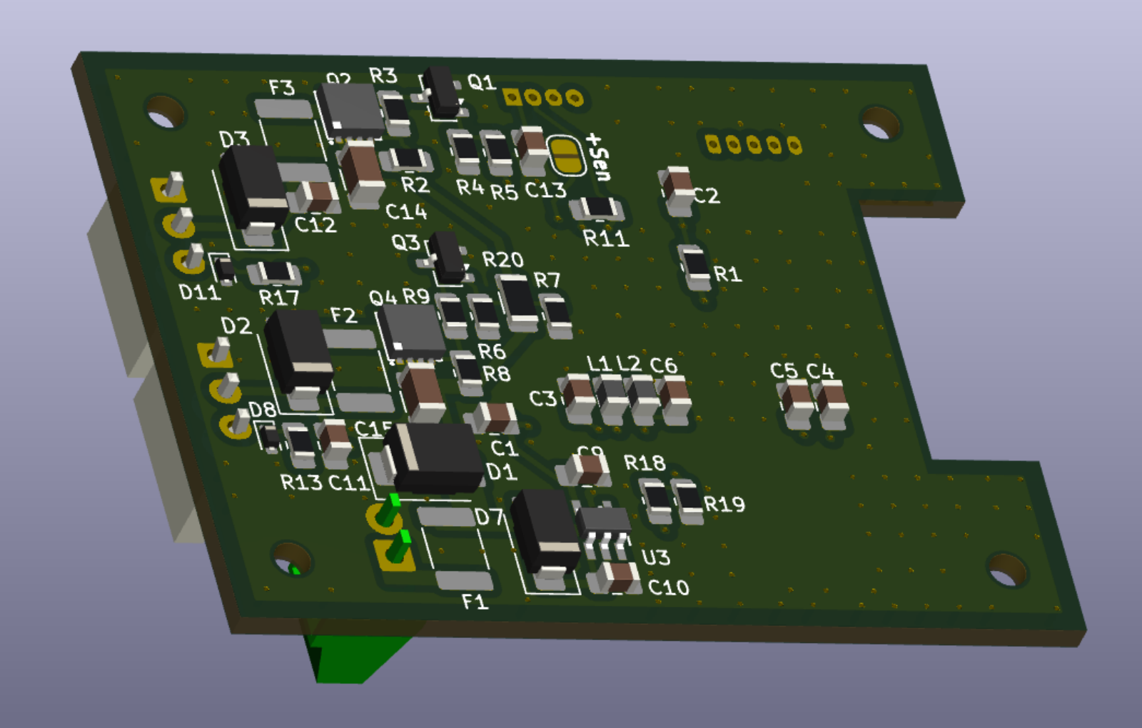
2 layers52.1 × 39.5 mmVentole Nrf52, the printed circuit board in 3D

progetto per il controllo delle ventole frigo con controllo via bluethooth basato su NRF52832 della nordic semiconductor e basato su Zephyr O.S.

Size
52.1 × 39.5 mm
Copper layers
2
Thickness
1.6 mm
Parts
62
Nets
63
Pads
180
Tracks, vias
263, 212
Pours
13
Routed
Yes
KiCad
KiCad 9.0 (file 20241229)
Created
21 Jun 2026
Updated
13 Jul 2026

Overview

Ventole Nrf52 is an open-source printed circuit board by JocoPippo, from the JocoPippo/nrf_FanFrigo repository on GitHub. It is a 2-layer board of 52.1 × 39.5 mm with 62 parts on 63 nets, routed with 263 tracks and 212 vias.

It is built around the TPS70933DBVR-MS, AP30P30Q and BC817, with the ESD5Z3.3T1G and SMBJ14A among its other parts. Its parts include 18 resistors, 13 capacitors, 9 diodes, 5 connectors and 4 transistors. It belongs with the nRF52 and nRF5x boards of this library.

Main components

5

README

README.md

Introduzione

In estate il frigo trivalente soffre molto a causa delle alte temperature che non consentono un scambio termico adeguato della serpentina di raffreddamente. In commercio esistono soluzioni ma queste sono pienamente soddisfacenti. Così ho deciso di realizzare una soluzione che permetesse di:

  • regolare la velocità delle ventole in base alla temperature del vano;
  • monitorare e controllare da remoto lo stato della board;
  • la seconda ventola, sen non forzata da applicativo, viene attivata quando la prima supera la soglia del 70% di utilizzo così da ridurre la rumorosità;
  • non pesare sui consumi elettrici quando non necessario.

La cartella "pheripheral_frigo" contiene il progetto per "Visual studio Code" del firmware della board di gestione delle ventole. La cartella hardware contiene il progetto in Kicad 9 e i file gerber della scheda di controllo. "AndroidApp" contiene l'applicativo Android di gestione della board. Ci si riferisca al file README.md interno a ciascuna cartella per dettagli specifici.

BOARD

Attualmente la revisione del pcb è la 2.0 in cui è stato aggiunto il supporto per il sensore tachimetrico per ciascuna ventola e la possibilità di valutare la tensione della batteria. Al fine di mantenere i consumi bassi si è scelto di inserire il partitore di tensione sotto il mosfet di controllo della ventola1. Questa scelta, benchè renda più semplice il pcb, complica la parte software che è ancora in fase di sviluppo. Probabilmente verrà sostituta aggiungendo un ulteriore switch. Vista lato superiore
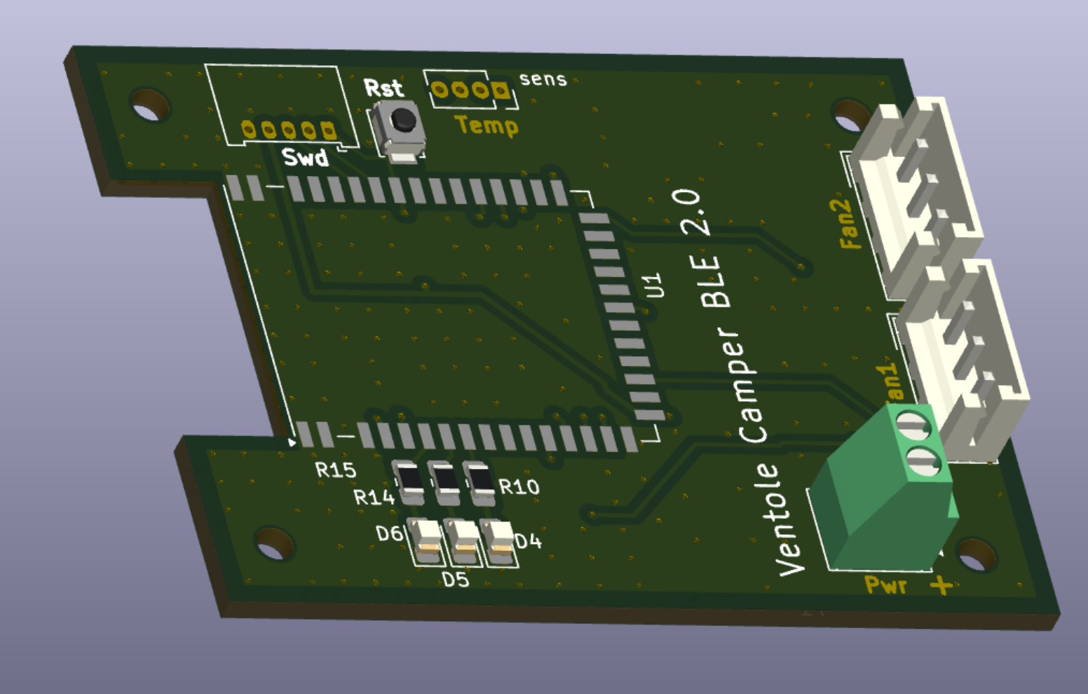
Vista lato inferiore

SOFTWARE GESTIONE

Basato sull'esempio "NRF Blinky" della nordic semiconductor è stato customizzato aggiungendo le funzionalità di riservatezza e di gestione della board.

La pagina di gestione consente di vedere lo stato corrente ed, eventualmente, di forzarlo. pagina di gestione
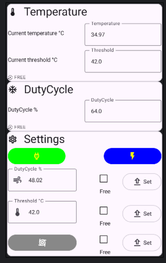
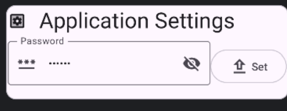
Nella pagina di settings si può cambiare la password che avrà valore transitorio fino al nuovo reset della scheda o tramite il ciclo power-off -> power-on o attraverso la pressione del tasto di reset. pagina di settings
Parts

62
QtyValueFootprintReferences
4100KResistor_SMD:R_0805_2012Metric_Pad1.20x1.40mm_HandSolderR1, R4, R7, R19
4MountingHoleMountingHole:MountingHole_2.2mm_M2H1, H2, H3, H4
30.1uCapacitor_SMD:C_0805_2012Metric_Pad1.18x1.45mm_HandSolderC2, C3, C13
31N4002Diode_SMD:D_SMAD2, D3, D7
3270Resistor_SMD:R_0805_2012Metric_Pad1.20x1.40mm_HandSolderR10, R14, R15
34.7uCapacitor_SMD:C_0805_2012Metric_Pad1.18x1.45mm_HandSolderC1, C9, C10
21.2KResistor_SMD:R_0805_2012Metric_Pad1.20x1.40mm_HandSolderR3, R9
21KResistor_SMD:R_0805_2012Metric_Pad1.20x1.40mm_HandSolderR13, R17
21nCapacitor_SMD:C_0805_2012Metric_Pad1.18x1.45mm_HandSolderC11, C12
21uCapacitor_SMD:C_1206_3216MetricC14, C15
222KResistor_SMD:R_0805_2012Metric_Pad1.20x1.40mm_HandSolderR5, R6
2500mAFuse:Fuse_1812_4532Metric_Pad1.30x3.40mm_HandSolderF2, F3
2750Resistor_SMD:R_0805_2012Metric_Pad1.20x1.40mm_HandSolderR2, R8
2AP30P30Qpcb:DFN-8_3.0x3.0-E0.65_mosQ2, Q4
2BC817Package_TO_SOT_SMD:SOT-23Q1, Q3
2ESD5Z3.3T1Diode_SMD:D_SOD-523D8, D11
10Resistor_SMD:R_1206_3216MetricR20
11.1AFuse:Fuse_1812_4532Metric_Pad1.30x3.40mm_HandSolderF1
1100pCapacitor_SMD:C_0805_2012Metric_Pad1.18x1.45mm_HandSolderC5
110uHInductor_SMD:L_0805_2012Metric_Pad1.05x1.20mm_HandSolderL2
115nHInductor_SMD:L_0805_2012Metric_Pad1.05x1.20mm_HandSolderL1
11uCapacitor_SMD:C_0805_2012Metric_Pad1.18x1.45mm_HandSolderC6
1390KResistor_SMD:R_0805_2012Metric_Pad1.20x1.40mm_HandSolderR18
15.6kResistor_SMD:R_0805_2012Metric_Pad1.20x1.40mm_HandSolderR11
1E73-2G4M04S-52832RF_Module:E73-2G4M04SU1
1Fan1Connector_JST:JST_EH_B3B-EH-A_1x03_P2.50mm_VerticalJ2
1Fan2Connector_JST:JST_EH_B3B-EH-A_1x03_P2.50mm_VerticalJ3
1LED1LED_SMD:LED_0805_2012Metric_Pad1.15x1.40mm_HandSolderD4
1LED2LED_SMD:LED_0805_2012Metric_Pad1.15x1.40mm_HandSolderD5
1LED3LED_SMD:LED_0805_2012Metric_Pad1.15x1.40mm_HandSolderD6
1N.C.Capacitor_SMD:C_0805_2012Metric_Pad1.18x1.45mm_HandSolderC4
1PWR_INpcb:TerminalBlock_MX128-2-2.54_1x02_P2.54mm_HorizontalJ1
1PowerSensorJumper:SolderJumper-2_P1.3mm_Open_RoundedPad1.0x1.5mmJP1
1ProgrammerConnector_Molex:Molex_PicoBlade_53048-0510_1x05_P1.25mm_HorizontalJ6
1RSTButton_Switch_SMD:SW_SPST_B3U-1000PSW1
1SMBj14ADiode_SMD:D_SMBD1
1TPS70933DBVRpcb:DBV5_TEX-MU3
1senspcb:PinSocket_1x04_P1.27mm_VerticalJ7

Similar boards

  • 2 layers237 × 139.1 mmMothbox 5.0.6, the printed circuit board in 3D

    Mothbox 5.0.6

    Digital-Naturalism-Laboratories/Mothbox_Electronics

    This is where the electronics for the Mothbox are developed, such as the PCB! It's copied over from https://github.com/Digital-Naturalism-Laboratories/Mothbox/tree/main/Hardware/PCB so you can check that out if you want…

    185 parts3MIT
  • 2 layers100 × 100 mmFuentes, the printed circuit board in 3D

    Fuentes

    darioGg3/PowerSuppliesTester

    97 parts1GPL-3.0
  • 2 layers152.4 × 142.2 mmEsp32 bluetooth, the printed circuit board in 3D

    Esp32 bluetooth

    silelis/MustangRadio_develepementVersion

    127 parts
  • 4 layers51.4 × 31.4 mmRP2350, the printed circuit board in 3D

    RP2350

    engelberd/sensor-system

    Working notes for the first custom RP2350A board with ADXL355, USB-C development power/data, 12 V field input, RS485, and a power architecture biased toward a clean accelerometer supply.

    87 parts2
  • 4 layers120 × 75 mmRedcat51ii flat panel controller revc, the printed circuit board in 3D

    Redcat51ii flat panel controller revc

    pulikantitarun/redcat51ii-automated-flat-panel

    Automated flat panel controller, PCB, firmware, and 3D-printable hardware for the William Optics RedCat 51 II and ASIAIR Plus

    68 parts2AGPL-3.0
  • 4 layers90.5 × 67 mmAS 4, the printed circuit board in 3D

    AS 4

    beaked99/air-scales

    2025-11-20. Updated all the footprints and symbols to their proper layouts. no more fkn errors. Hallefuckinglujah. Fucked up with LM74610 not using the right footprint. minor fix. 2025-11-16.

    131 parts
  • 4 layers44.5 × 26.5 mmTelemetry node-12V module, the printed circuit board in 3D

    Telemetry node-12V module

    bquangDinh/telemetry-node-12V-module

    Board layout for telemetry node 12V module. This module will help power the board using 12V in case it needs 12V input

    26 parts

Questions

How big is the Ventole Nrf52 PCB?

It measures 52.1 × 39.5 mm and has 2 copper layers, 1.6 mm thick.

What parts does the Ventole Nrf52 use?

62 parts, built around the TPS70933DBVR-MS, AP30P30Q, BC817 and ESD5Z3.3T1G. The full list of its parts is on this page, with links to each part's symbol and footprint where PCBKit's library has them.

Where can I download the Ventole Nrf52 KiCad files?

From the JocoPippo/nrf_FanFrigo repository on GitHub, at the commit this page was made from: the board is hardware/Ventole_Nrf52/Ventole_Nrf52.kicad_pcb and its schematic hardware/Ventole_Nrf52/Ventole_Nrf52.kicad_sch. PCBKit opens the board in the browser, with nothing to install.

Can I use the Ventole Nrf52 design in my own project?

Its repository states no licence, so its author keeps all rights: ask JocoPippo before reusing the design.