2 layers85.6 × 26 mm
Game boy pico link board
agtbaskara/game-boy-pico-link-board
An Open-Source USB to Gameboy Link Cable Adapter for Raspberry Pi Pico
6 parts51MIT
 JhouLab/Pi5WebcamRecorder1
Records MV4 AVI video files from up to 4 simultaneous USB webcams on Raspberry Pi 5
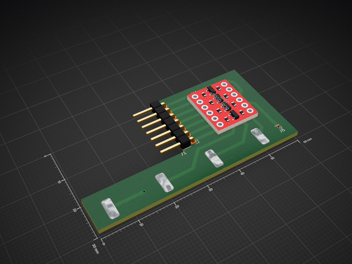
GPIO circuit is an open-source printed circuit board by JhouLab, from the JhouLab/Pi5WebcamRecorder repository on GitHub. It is a 2-layer board of 60 × 30 mm with 7 parts on 11 nets, routed with 44 tracks and 2 vias.
It is built around the BOB-12009. Its parts include 6 connectors and 1 IC.
Instructions, version 1.5, Updated March 10, 2025.
This is intended to run on a Raspberry Pi 5, which is much faster than the Pi 4. It can handle 4 simultaneous cameras at 640x480 resolution and 30 frames per second.
It will run on an older Pi 4 (slowly), and is best suited for controlling a single camera.
If you have problems, questions, or suggestions, please email jhoulab1@gmail.com
To install on a new machine, follow the instructions at the bottom of this page, under: "Installing on Raspberry Pi 5".
On most JhouLab Pi's, the program is already installed to the following folder:
/home/jhoulab/Documents/github/Pi5WebcamRecorderOnce installed, launch the program with one of the following methods:
Method 1: From command line:

  cd ~/Documents/github/Pi5WebcamRecorder
  python -m RUN_AS_ROOT

Method 2: From the Pi's built-in Thonny app:
  Click "Load", select "RUN_AS_ROOT.py", then click "Run" (green button with white triangle).
Upon launch, the program will auto-detect USB cameras, open a control bar, and display up to 4 cameras in a 2x2 grid, like below:
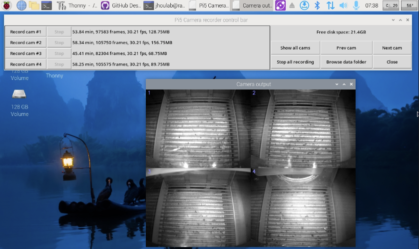
Cameras plugged into any of the four USB ports will show up on the screen in the following positions:
-------------
|  1  |  2  |
-------------
|  3  |  4  |
-------------
The program will show a bar at the top with buttons to start/stop recording. You can also control recording from external GPIO logic inputs (see "GPIO PROTOCOL" section below).
By default, videos save to the program directory, but I recommend you change this to an external drive, to avoid filling up your SD card. This is done by creating/editing a config.txt file (see CONFIGURING section below).
Default video format is 640x480, 30fps, with h264 encoding. These can also be changed in config.txt.
Each recording session generates three files, with the following names and contents:
YYYY-MM-DD_HHmm_CamX_AnimalID_Video.avi     # Video file in h264 format.
YYYY-MM-DD_HHmm_CamX_AnimalID_Frames.txt    # Tab-delimited text file with timestamps of each video frame
YYYY-MM-DD_HHmm_CamX_AnimalID_TTLs.txt      # Tab-delimited text file with timestamps of each TTL pulse
In the above filenames, YYYY-MM-DD_HHmm is the date and time, X is the camera number (1-4), and AnimalID is entered manually or transmitted via GPIO logic inputs.
h264 codec is pretty efficient. Files are typically about 2MB/min, or 33kB/sec. This will reach 1GB after about 6-8 hours.
Many default parameters can be changed using a "config.txt" text file. I've included two working examples:
config_example1     A detailed file with all possible configuration options
config_example2     A bare-bones file with only the most commonly used options.
To use either file, open it in any text editor, resave it as "config.txt", then edit to suit your needs. Changes to "config.txt" take effect only after restarting the program. Options include the following:
RECORD_FRAME_RATE            # Frame rate of recorded video. If not specified, defaults to camera's native frame rate, typically 30fps
NATIVE_FRAME_RATE            # Native frame rate of webcam. If not specified, will be auto-detected.
DATA_FOLDER                  # Folder for saving. If not specified, defaults to program directory.
RESOLUTION                   # A string of the form: (width,height), e.g. (640x480)
FOURCC # Recording codec. Default h264 which gives smallest file sizes. Can also use mp4v, which is less CPU intensive, but gives larger filesPi5WebcamRecorder monitors GPIO inputs 4 through 7, corresponding to the following cameras:
GPIO4:          camera 1
GPIO5:          camera 2
GPIO6:          camera 3
GPIO7:          camera 4
These are 3.3V inputs, so you must use a level shifter when connecting to 5V devices. If you use Med-PC to generate timing signals, remember that those are 28V signals, which require an additional voltage shifter (purchased from Med Associates) to convert from 28V to 5V, which in turn is converted to 3.3V through the level-shifter, i.e. you will need to devices. Setting these up requires some familiarity with electronics.
Sending two consecutive 100ms pulses (with a 50ms pause in between) will start a recording, as follows:
        100ms  100ms
3.3V     ___    ___
        |   |  |   |
0V -----     --     --------
            50ms
Once a session is started, three consecutive 100ms pulses will stop the recording:
        100ms  100ms  100ms
3.3V     ___    ___    ___
        |   |  |   |  |   |
0V -----     --     --     ----
            50ms    50ms
While a recording is ongoing, any single 100ms pulse will be recorded in the *_TTLs.txt file. The pulse will look like this:
        100ms
3.3V     ___
        |   |
0V -----     ----------
The contents of the *_TTLs.txt file will be tab-delimited, and will will have three columns, corresponding to event number, onset time, and offset time:
TTL_event_number	ONSET (seconds)	OFFSET (seconds)
1	19.604753732681274	19.708051204681396
2	155.62897396087646	155.73339176177979
3	411.64712834358215	411.75243949890137
4	607.6641576290131	607.7683758735657
5	803.6808965206146	803.7854342460632
6	1059.6991975307465	1059.8032557964325
With all pulses, the allowable range is 50-150ms, but it is recommended not to get too close to the endpoints of this range, as errors can occur due to Linux not being a real-time operating system.
You can also transmit an animal ID number via the GPIO pins as a 16-bit binary number. The ID number has to be transmitted BEFORE starting the session, and will show up in the filename and on the screen during recording.
If you transmit the ID after a session has already started, it will likely get interpreted as a triple pulse, which will stop the recording. So don't do that.
ID transmission begins with a 300ms pulse, followed by 16 binary bits as shown below:
3.3V      300ms  <16 binary bits, 50 or 150ms each>            <Parity bit 50 or 150ms long>
         ______   _   _   ___   _   ___                 _       _
        |      | | | | | |   | | | |   |  .. etc..     | |     | |
0V -----        -   -   -     -   -     -             -   -----   ---------------
                  50ms between ID bits                    200ms pause before parity bit
The bit order is MOST significant bit first, 50ms pulse for "0" and 150ms pulse for "1", and 50ms gaps between pulses. The final checksum parity bit is 50ms duration if the preceding ID had an even number of "1"s, 150ms duration if odd.
The last frame of video may not be recorded to the hard drive. This appears to be a bug in FFMPEG, which OpenCV uses.
On Windows, it is convenient to use ImageJ/FIJI to quickly view videos, but this does not appear to work on the Raspberry Pi, again due to issues with FFMPEG. A cumbersome workaround is to decompress video using:
ffmpeg input.avi -c:v rawvideo output.aviTo install, follow these three steps:
There are two ways to do this:
git clone https://github.com/JhouLab/Pi5WebcamRecorderFirst install Pi-Apps:
wget -qO- https://raw.githubusercontent.com/Botspot/pi-apps/master/install | bashLaunch Pi-Apps, select "Programming", "Github Desktop" (the purple cat icon), and click "Install". It will take a couple of minutes. Then launch Github from the main Raspberry Pi menu, under "Accessories", then log into the lab github account. Then select "File", "Clone repository", "Github.com", "JhouLab/Pi5WebcamRecorder":
Github Desktop only works on Pis running a 64-bit os. If you are running a 32-bit os, it may still install, but graphics will be weird and unusable.
From the command prompt, type the following:
sudo apt-get install libopencv-dev
sudo apt-get install python3-opencv
As of 6/12/2024, this installs OpenCV version 4.6.0, which is outdated (released 6/12/2022), but works well enough. For other ways to install OpenCV, see here: https://qengineering.eu/install%20opencv%20on%20raspberry%20pi%205.html
The Pi5 uses different GPIO hardware than the Pi4, but the default GPIO library up to 2023 assumed the old hardware, requiring one to manually replace it with python3-rpi-lpgio. Starting in late 2023 with Bookworm OS, this is no longer required as it is included by default:
sudo apt remove  python3-rpi.gpio
sudo apt install python3-rpi-lgpioFrom the command line, install both:
sudo apt upgrade
sudo apt install cifs-utils smbclient -y
curl -fsSL https://tailscale.com/install.sh | sh
sudo tailscale up
When you run this, it should open a browser window into which you should log into the lab tailscale account. If not, you will see a link that you can right click to manually open. Then sign into your tailscale account. It might take a couple of tries for this to work. When done, the console window should report "Success." and return you to the Linux prompt. If you don't see that, it didn't work yet.
After this, it will automatically reconnect when rebooting Pi, and you don't need to restart it again.
Optional: can use this to prevent tailscale up from requiring sudo
sudo tailscale set --operator=$USERNow install smb client:
sudo apt-get install samba-common smbclient samba-common-bin smbclient cifs-utilsMake folder and mount shared folder there. The mount does not persist after Pi restart:
sudo mkdir /mnt/share_name_here
sudo mount -t cifs //labunraid/zfs48_share /mnt/share_name_here -o user=tomjhou,pass=ithaca55,uid=1000,gid=1000
To ensure this works every time, add the following line to config.txt:
LINUX_START_SCRIPT = sudo mkdir -p /mnt/share_name_here && sudo mount -t cifs //labunraid/zfs48_share /mnt/share_name_here -o user=tomjhou,pass=ithaca55,uid=1000,gid=1000Note the mkdir "-p" option to suppress error if folder already exists. Somehow on raspberry pi, mount will still run even if mkdir throws error. Not sure why, as "&&" shouldn't allow that. Not actually a problem, just curious behavior. If mount exists, will throw "device or resource busy error". This can be safely ignored.
| Qty | Value | Footprint | References |
|---|---|---|---|
| 4 | Conn_01x01 | GPIO_footprints:Pad_for_BNC | J2, J3, J4, J5 |
| 1 | BOB-12009 | GPIO_footprints:CONV_BOB-12009 | U1 |
| 1 | Conn_01x01 | Connector_PinHeader_1.00mm:PinHeader_1x01_P1.00mm_Vertical | J6 |
| 1 | Conn_01x07 | Connector_PinHeader_2.54mm:PinHeader_1x07_P2.54mm_Horizontal | J1 |
agtbaskara/game-boy-pico-link-board
An Open-Source USB to Gameboy Link Cable Adapter for Raspberry Pi Pico


VincentKobz/diy-weather-station
The goal is to build from scratch a small intelligent weather station that can be connected to IOT networks.


hselomein/Car-LED-Controller
This is a private repo for my car led project

michelkeijzers/fraxis
This project's personal goal is to learn more about ESP32 with ESP-IDF programming.

It measures 60 × 30 mm and has 2 copper layers, 1.6 mm thick.
7 parts, built around the BOB-12009. The full list of its parts is on this page, with links to each part's symbol and footprint where PCBKit's library has them.
From the JhouLab/Pi5WebcamRecorder repository on GitHub, at the commit this page was made from: the board is GPIO_circuit/GPIO_circuit.kicad_pcb and its schematic GPIO_circuit/GPIO_circuit.kicad_sch. PCBKit opens the board in the browser, with nothing to install.
Its repository states no licence, so its author keeps all rights: ask JhouLab before reusing the design.