4 layers21 × 20 mm

 JeremyMParker/Amiga500-Mod-PCB-Project6
A small back panel PCB to house HDMI and several switches...
Amiga500 Mod PCB Rev A is an open-source printed circuit board by JeremyMParker, from the JeremyMParker/Amiga500-Mod-PCB-Project repository on GitHub. It is a 4-layer board of 71.4 × 24.9 mm with 11 parts on 38 nets, routed with 163 tracks and 28 vias.
Its parts include 7 connectors and 3 switches.
A small back panel PCB to house HDMI and several switches...
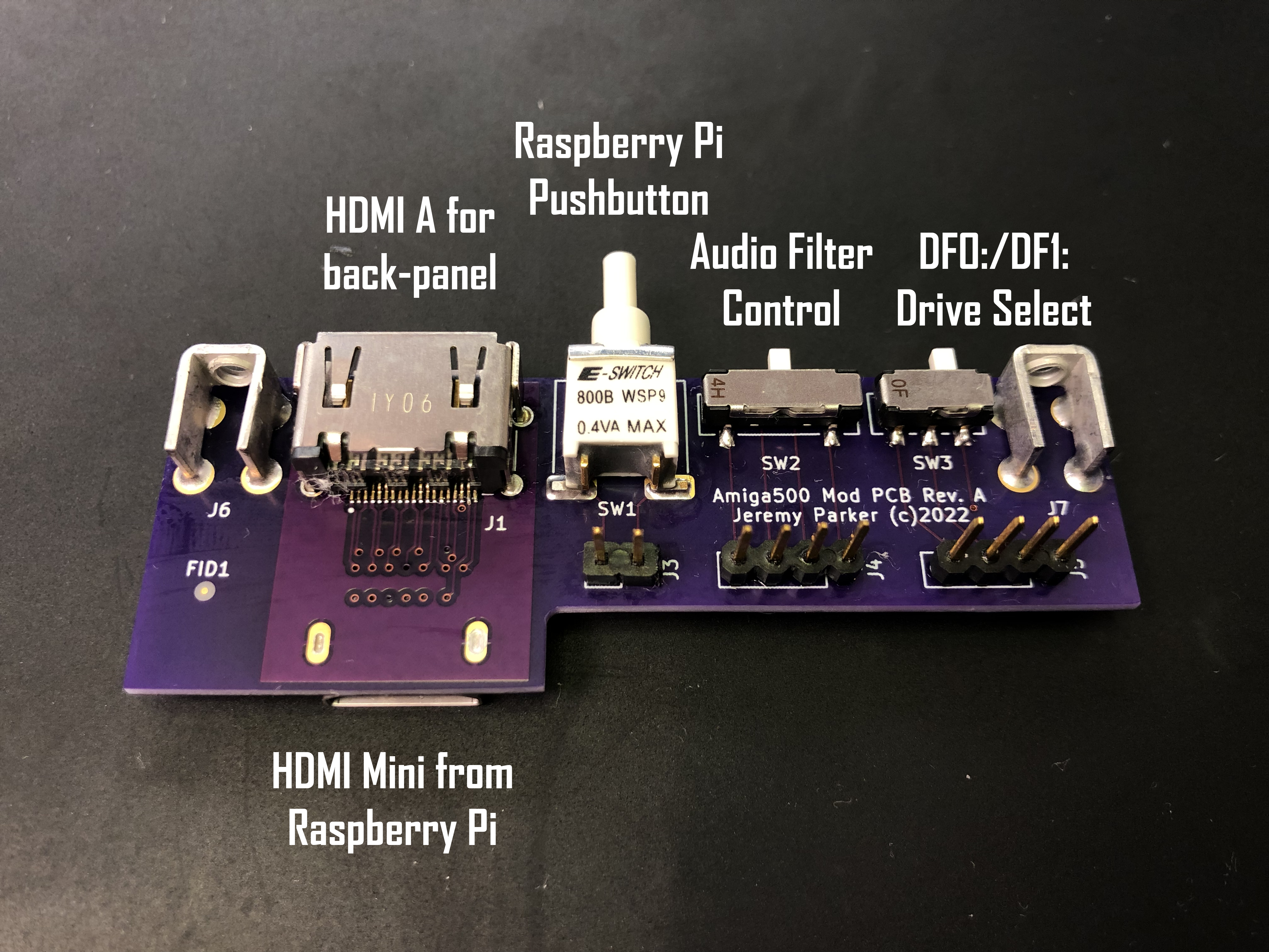
This small 4-layer PCB will take an HDMI mini cable from a Raspberry Pi RGB-to-HDMI and convert to normal size HDMI for plugging into the Amiga.
There is one small SPST push-button switch to allow menu access to the Raspberry Pi by way of a 2-pin 100mil spaced header.
A miniture DPDT switch is wired to a 4-pin 100mil header to allow the Amiga-Kit DF0/DF1 select switch cable to plug right in.
A miniture 3PDT switch is wired to a 4-pin 100mil header to allow access to the Amiga Audio Filter Mod as described in my YouTube video.
The Audio Filter control either lets the Amiga control the output low-pass filters, or overrides the Amiga and forces the filters to be enabled/disabled.
The PCB is just barely wide enough to fit in the blank space on the left side of the A500 when looking at the back.
This is my first GitHub repository, so please be patient with me!
| Qty | Value | Footprint | References |
|---|---|---|---|
| 2 | Conn_01x04_Male | Connector_PinHeader_2.54mm:PinHeader_1x04_P2.54mm_Vertical | J4, J5 |
| 2 | Screw_Terminal_01x04 | JP Library:Keystone 4-40 screw terminal | J6, J7 |
| 1 | 2013978-1 | SnapEDA Library:TE_2013978-1 | J2 |
| 1 | Conn_01x02_Male | Connector_PinHeader_2.54mm:PinHeader_1x02_P2.54mm_Vertical | J3 |
| 1 | DC04S019JA1R600 | SnapEDA Library:JAE_DC04S019JA1R600 | J1 |
| 1 | Fiducial | Fiducial:Fiducial_0.5mm_Mask1.5mm | FID1 |
| 1 | SW_DPDT_x2 | JP Library:DPDT CL-SB-22B-12T | SW3 |
| 1 | SW_Push | JP Library:SPST 800BWSP9SM6RE | SW1 |
| 1 | SW_SP3T | JP Library:SP3T CL-SB-13B-11T | SW2 |

clydeshaffer/gametank
design files for the gametank hardware implementation

Unified-Daughterboard/UDB-S
Narrow variant unified daughterboards for custom keyboard designers and users

matthuszagh/fmcw
6GHz frequency-modulated continuous-wave radar with real-time range detection


efabless/caravel_board
This repo provides firmware examples, flash programming and diagnostic tools for testing Open MPW and chipIgnite projects using Caravel.

RetroRemake/OtterX
8-Bit computer compatible with Commander X16

It measures 71.4 × 24.9 mm and has 4 copper layers, 1.75 mm thick.
11 parts. The full list of its parts is on this page, with links to each part's symbol and footprint where PCBKit's library has them.
From the JeremyMParker/Amiga500-Mod-PCB-Project repository on GitHub, at the commit this page was made from: the board is Amiga500 Mod PCB Rev A.kicad_pcb and its schematic Amiga500 Mod PCB Rev A.kicad_sch. PCBKit opens the board in the browser, with nothing to install.
Its repository states no licence, so its author keeps all rights: ask JeremyMParker before reusing the design.