2 layers100 × 100 mm

 JX5S/DP_aux_emulator48
Board for modifying traffic on DP-aux. Specifically, board is made for correcting false information provided by the PSVR2 making it not work on PC. Except for DP-aux, it is a passive extension of USB-C.
DP Aux MITM V0 is an open-source printed circuit board by JX5S, from the JX5S/DP_aux_emulator repository on GitHub, published under the MIT licence. It is a 6-layer board of 47 × 30 mm with 87 parts on 87 nets, routed with 600 tracks and 168 vias.
It is built around the RP2040, TPS54202DDC and SN65MLVD200A, with the BZT52C4V3SQ and SS14 among its other parts. Its parts include 28 resistors, 27 capacitors, 8 connectors, 6 diodes and 5 ICs. It belongs with the RP2040 boards of this library.


Hardware design files for a DP-aux emulation board, designed to allow connection of PSVR2 headsets to PC.
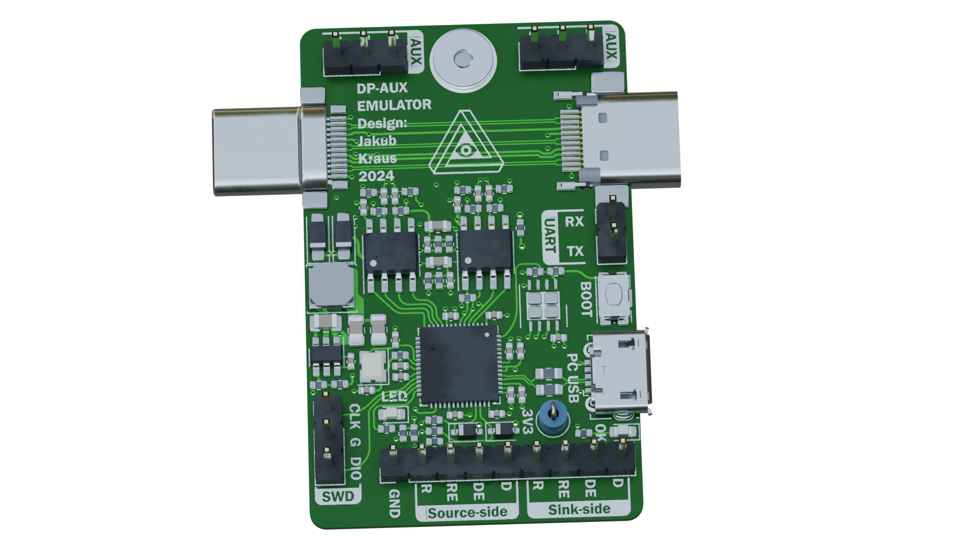
Prior to a March 2024 update of the PSVR2's firmware, the headset reported incorrect information via DP-aux, among others the EDID and DSC capability. A custom EDID can be set without additional hardware, however DSC options cannot be - so the emulator board was born.
Since this board was built, Sony released firmware update(s) to the PSVR2, which corrected the lies and allow connection to GPUs directly. While this emulator is still useful for enabling "cinema" mode and for future experiments, such as possibly enabling HDR support, most users won't need it.
This board is only for modifying traffic on DP-aux, it doesn't help if your GPU doesn't have a USB-C port. Sony is releasing an adapter for that soon, I have no reason to believe it wouldn't work with 3rd party drivers.
This is a third revision of the PCB, it has been verified to work as designed.
The board was designed for JLCPCB's assembly. The necessary files are in the 'Manufacturing data' folder. The zip file is there for a quick download of just those 3 files. The files are:
The only settings that need changing from defaults during ordering at JLCPCB are PCB thickness (0.8mm) and impedance control (Yes; JLC06081H-2116). Detailed screenshots of all settings including defaults are in the 'JLCPCB settings' folder.
The 4th image shows edge-rail cut-outs which need to be added to allow surface mounting of these specific USB-C connectors. These can be added by JLC (you do need to explicitly request them), or you can add them yourself in KiCad, or you can have the edge-rails removed and the USB-C connectors added afterwards (JLC will build a mounting adapter for the board at additional cost).
Firmware was written by the autor of the iVRy SteamVR driver. A passthrough-only version of the firmware is provided in this repository for testing, a PSVR2-specific firmware is distributed along with the iVRy PSVR2 driver.
A case has been designed for the DP-AUX emulator by "Hackinside". They have kindly made the files available for anyone that wants to print their own case.
On the PCB is an RP2040 microcontroller, which decides which DP-aux requests to modify and which to pass through unchanged. To interface with DP-aux, a pair of SN65MLVD200A differential transceivers are used. The LVDS part of the circuit is based on Bitec's DisplayPort Daughter Card.
Apart from the core DP-aux emulation circuitry, there is a programming micro-USB connector (I would have used a USB-C, but this way it cannot be confused with the PSVR2 port), orientation detection using USB-C CC pins, and a power section, allowing the board to be powered with either the programming USB port or using VBUS from the USB-Cs. Even though the board was made with specifically the PSVR2 in mind, I tried to make it as compliant as possible with a low part count and it should work well with the maximum voltage of USB-PD3.0, 21V.
| Qty | Value | Footprint | References |
|---|---|---|---|
| 16 | 100n | Capacitor_SMD:C_0402_1005Metric | C1, C4, C5, C10, C11, C12, C13, C14, C15, C16, C18, C19, C21, C22, C23, C24 |
| 7 | 10K | Resistor_SMD:R_0402_1005Metric | R1, R7, R8, R9, R17, R18, R28 |
| 4 | 1uF | Capacitor_SMD:C_0402_1005Metric | C6, C7, C8, C9 |
| 4 | 51R | Resistor_SMD:R_0402_1005Metric | R13, R14, R20, R21 |
| 3 | 100K | Resistor_SMD:R_0402_1005Metric | R22, R23, R26 |
| 3 | 1K | Resistor_SMD:R_0402_1005Metric | R2, R5, R10 |
| 2 | 10u | Capacitor_SMD:C_0603_1608Metric | C17, C25 |
| 2 | 15pF | Capacitor_SMD:C_0402_1005Metric | C2, C3 |
| 2 | 1K5 | Resistor_SMD:R_0402_1005Metric | R16, R25 |
| 2 | 1M | Resistor_SMD:R_0402_1005Metric | R11, R12 |
| 2 | 22u | Capacitor_SMD:C_0805_2012Metric | C27, C28 |
| 2 | 27R | Resistor_SMD:R_0603_1608Metric | R3, R4 |
| 2 | 3K3 | Resistor_SMD:R_0402_1005Metric | R15, R24 |
| 2 | 510R | Resistor_SMD:R_0402_1005Metric | R6, R19 |
| 2 | BZT52-C4V3S | USB-C_for_0.3:D_SOD-323 Panjit | D1, D3 |
| 2 | Blue | LED_SMD:LED_0603_1608Metric | D2, D7 |
| 2 | DP-AUX | Connector_PinHeader_2.54mm:PinHeader_1x03_P2.54mm_Vertical | J5, J7 |
| 2 | LOGO | Libraries:iVRy logo 8mm_silk | G***, G*** |
| 2 | SN65MLVD200A | Package_SO:SOIC-8_3.9x4.9mm_P1.27mm | U3, U5 |
| 2 | SS14 | USB-C_for_0.2:D_SOD-123FL | D4, D5 |
| 1 | W25Q64JVX | Package_SON:WSON-8-1EP_4x4mm_P0.8mm_EP2.6x3mm | U1 |
| 1 | 10u | Capacitor_SMD:C_0805_2012Metric | C26 |
| 1 | 12MHz 12pF | Crystal:Crystal_SMD_2520-4Pin_2.5x2.0mm | Y1 |
| 1 | 15u | Inductor_SMD:L_Sunlord_SWPA4018S | L1 |
| 1 | 22K | Resistor_SMD:R_0402_1005Metric | R27 |
| 1 | BOOT | USB-C_for_0.3:C&K KMR223GLFG | SW1 |
| 1 | DEBUG HEADER | Connector_PinHeader_2.54mm:PinHeader_1x09_P2.54mm_Vertical | J6 |
| 1 | Disable | Jumper:SolderJumper-2_P1.3mm_Open_RoundedPad1.0x1.5mm | JP1 |
| 1 | M2_SMTSO2010CTJ | M2nutV2:M2 solder nut | H1 |
| 1 | RP2040 | Package_DFN_QFN:QFN-56-1EP_7x7mm_P0.4mm_EP3.2x3.2mm | U2 |
| 1 | SWD | Connector_PinHeader_2.54mm:PinHeader_1x03_P2.54mm_Vertical | J2 |
| 1 | SolderJumper_2_Closed | Jumper:SolderJumper-2_P1.3mm_Bridged2Bar_RoundedPad1.0x1.5mm | JP3 |
| 1 | SolderJumper_3_Bridged12 | Jumper:SolderJumper-3_P1.3mm_Bridged2Bar12_RoundedPad1.0x1.5mm | JP2 |
| 1 | TPS54202DDC | Package_TO_SOT_SMD:SOT-23-6 | U6 |
| 1 | TestPoint | TestPoint:TestPoint_Loop_D1.80mm_Drill1.0mm_Beaded | TP3 |
| 1 | TestPoint | TestPoint:TestPoint_Pad_D2.0mm | TP1 |
| 1 | UART | Connector_PinHeader_2.54mm:PinHeader_1x02_P2.54mm_Vertical | J3 |
| 1 | USB_B_Micro | Connector_USB:USB_Micro-B_Molex-105017-0001 | J1 |
| 1 | USB_C_Plug | USB-C_for_0.3:USB_C_VirtualLink_Plug | J4 |
| 1 | USB_C_Receptacle | USB-C_for_0.3:USB_C_Straddle_Socket | J8 |
The 85 most common of 87 parts.

lhm0/rotating_display_color
56 LED rotating color display with RP2040 and ESP32 microcontrollers


nunosousa/TelescopeMirrorTester
This is an application intended to provide useful tools to perform Foucault or Wire testing on reflective telescope mirrors

OpenJBOD/rp2040
This repository contains the hardware design files OpenJBOD RP2040 Baseboard.

DevKiDCosmo/SATELLITE-EDGE-MODULE
A satellite edge module ready for competition

MitchellStride/Hummingbird-RP2040-Clock-Module
RP2040 RTC Module, highly compatible with JLCPCB's basic SMT components.
It measures 47 × 30 mm and has 6 copper layers, 0.8 mm thick.
87 parts, built around the RP2040, TPS54202DDC, SN65MLVD200A and BZT52C4V3SQ. The full list of its parts is on this page, with links to each part's symbol and footprint where PCBKit's library has them.
From the JX5S/DP_aux_emulator repository on GitHub, at the commit this page was made from: the board is DP-Aux_MITM_V0.kicad_pcb and its schematic DP-Aux_MITM_V0.kicad_sch. PCBKit opens the board in the browser, with nothing to install.
Its repository publishes it under the MIT licence: you may reuse it on that licence's terms (keep the author's notice, and for a copyleft licence share your changes alike).