6 layers133.1 × 133.1 mm
AERIS H743-PCB
7903555032/AERIS-H743-PCB
A 6-layer STM32H743-based embedded development and flight-control/data-logging PCB designed as a practical hardware-design and PCB-layout project.
114 parts1

 JEly613/Mini-LiDAR-Board1
Handheld LiDAR Room Scanner pcb
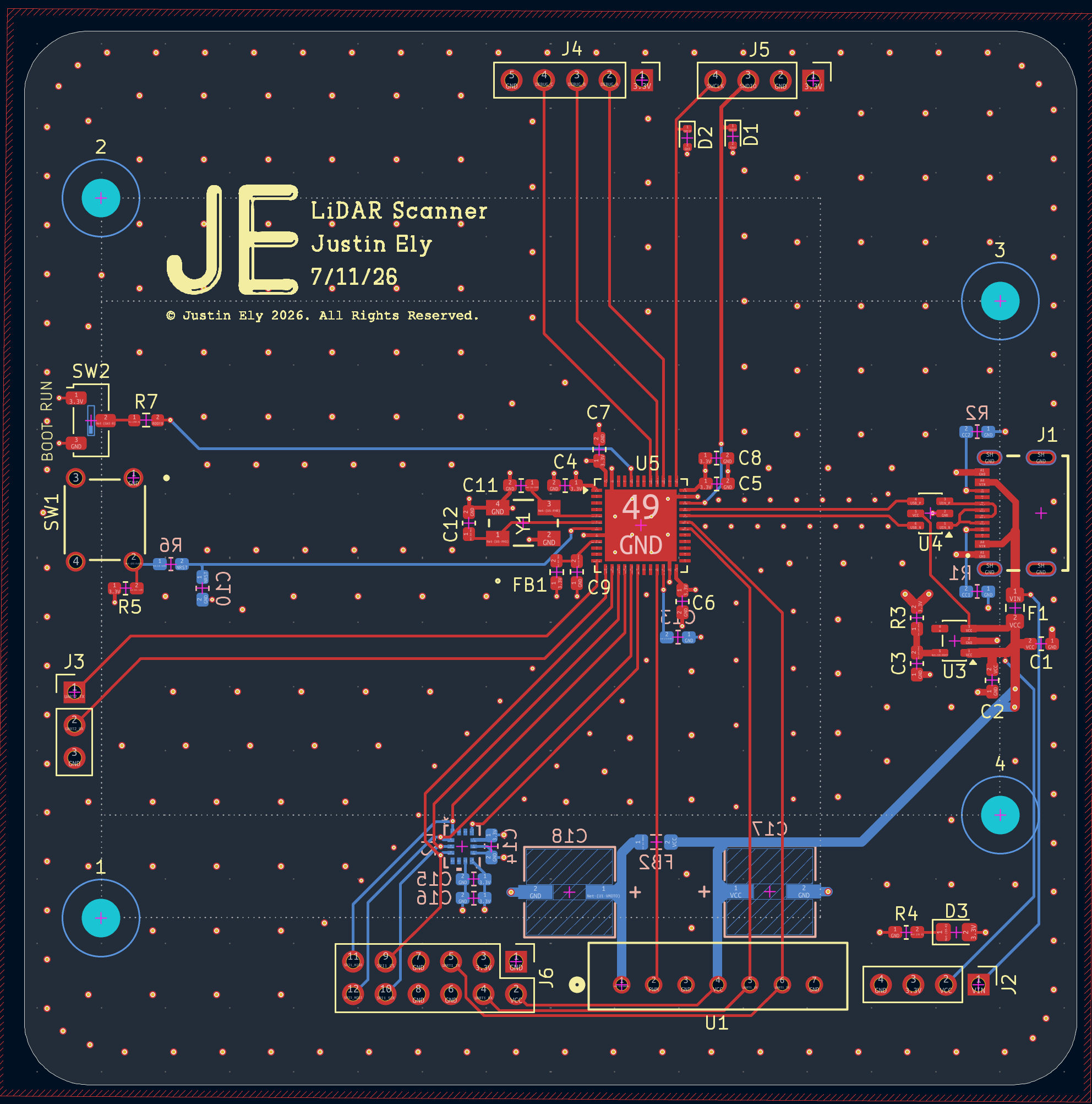
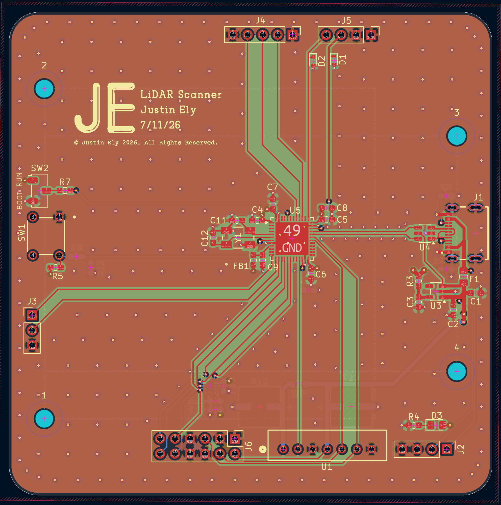
LiDAR Scanner is an open-source printed circuit board by JEly613, from the JEly613/Mini-LiDAR-Board repository on GitHub. It is a 4-layer board of 82 × 82 mm with 49 parts on 60 nets, routed with 324 tracks and 340 vias.
It is built around the AP2112K-3.3, ICM-42688-P and USBLC6-2SC6, with the USB4215-03-A among its other parts. Its parts include 18 capacitors, 7 resistors, 6 connectors, 5 ICs and 3 diodes. It belongs with the sensors and measurement boards and the STM32 boards of this library.


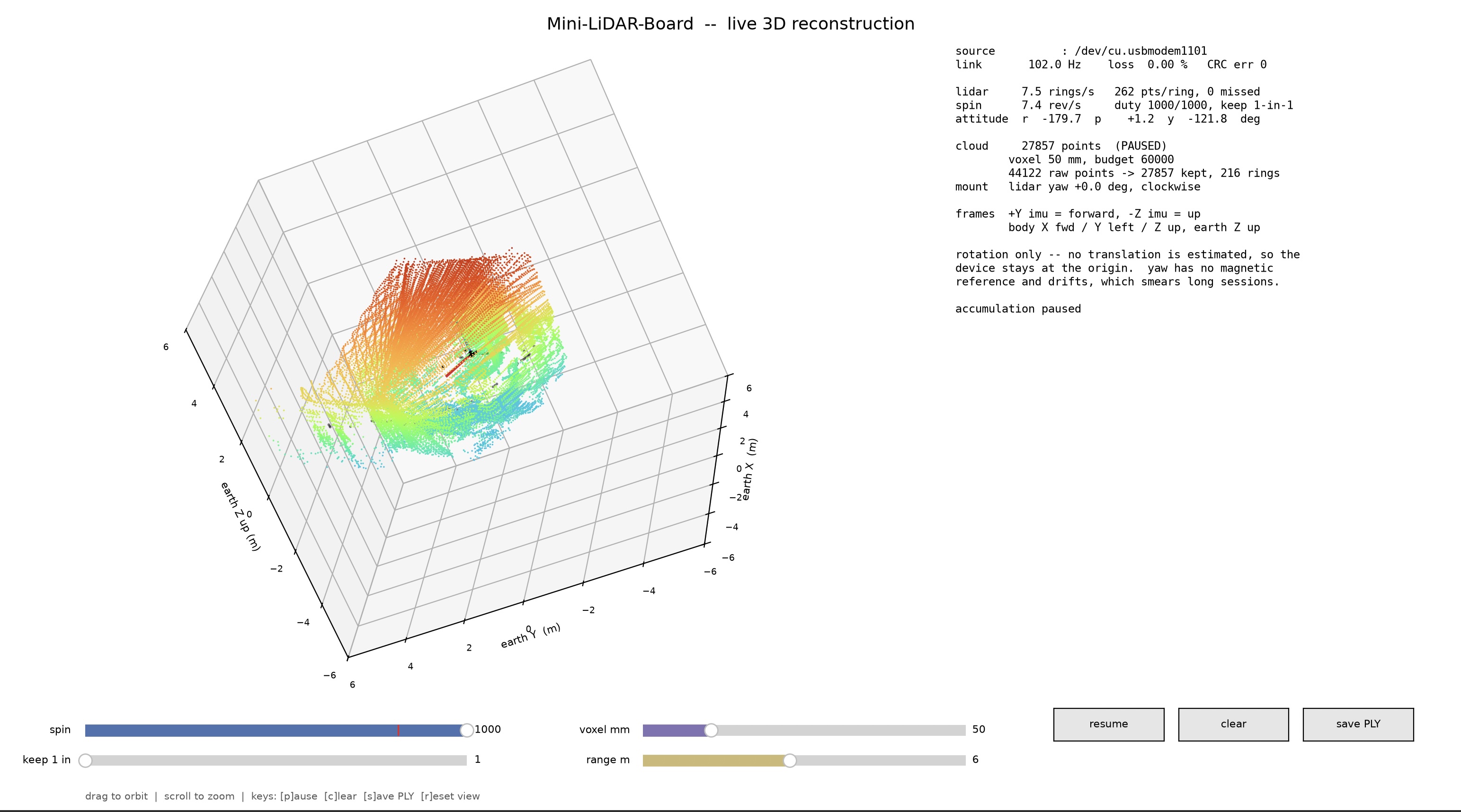
This project fuses data from LiDAR and IMU measurements to reconstruct internal scans of a room. The LiDAR module is mounted on a custom 4-layer PCB that hosts an STM32 microcontroller and an ICM-42688-P IMU. The data from both sensors is collected by the microcontroller and sent via a custom USB protocol to the host software, where the room is reconstructed.
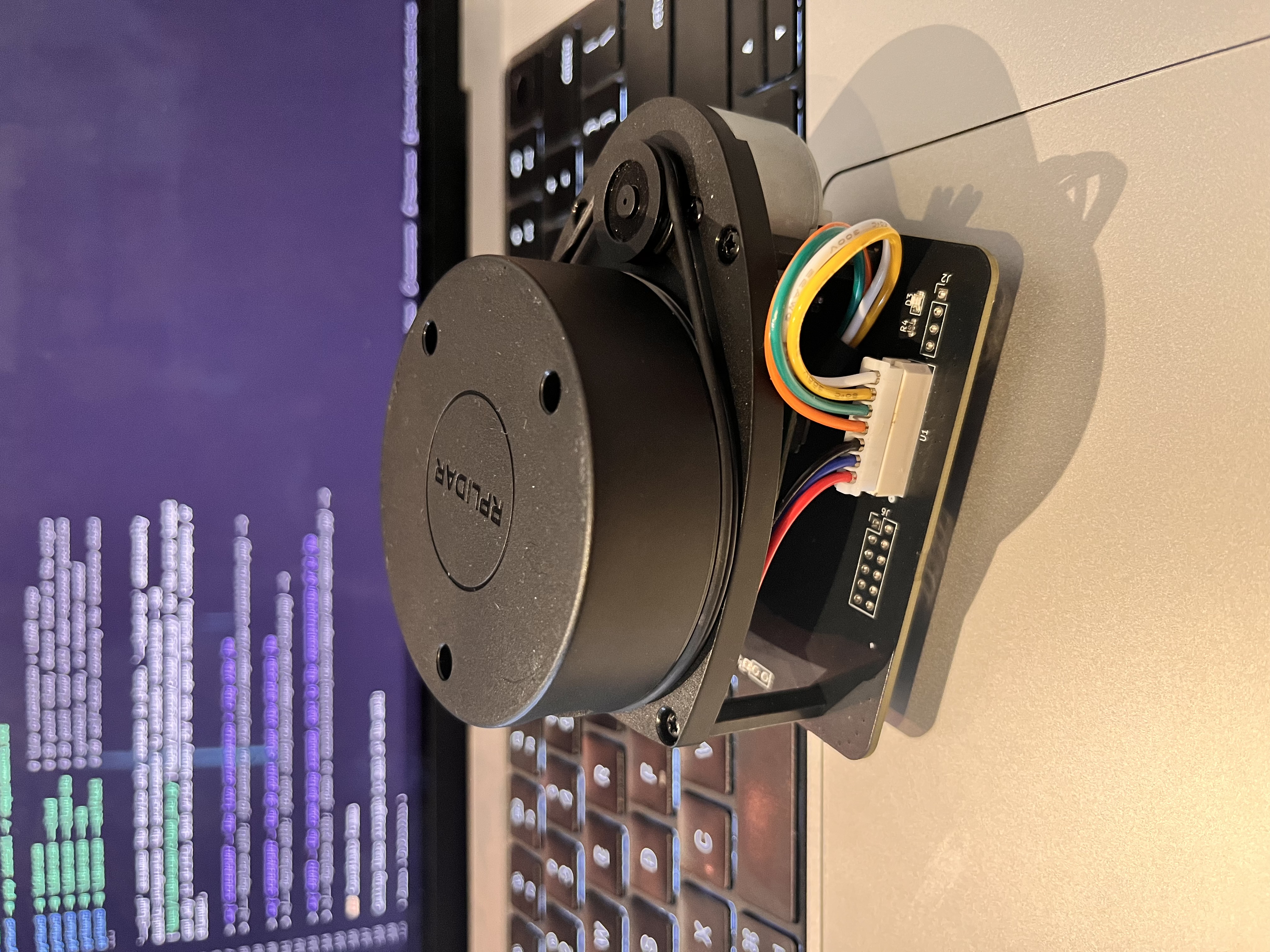
The board spins a LiDAR module that measures distances in a 2D plane. On its own that only ever produces a flat ring. The on-board IMU tracks how the boardis oriented, so every distance reading can be rotated out of the sensor's 2D plane and into a 3D environment. Tilting the sensor so that all 360 degrees of freedom are covered constructs a full scan of the room.
Designed using KiCad.
| Board | 4-layer, 82 × 82 mm, 49 components, 212 vias |
| Stackup | F.Cu signal · In1.Cu GND plane · In2.Cu VDD plane · B.Cu signal |
| MCU | STM32F411CEU6 — QFN-48, 7 × 7 mm, 0.5 mm pitch, 96 MHz |
| IMU | TDK ICM-42688-P — LGA-14, 2.5 × 3 mm, on SPI1 |
| LiDAR | Slamtec RPLIDAR A1, PWM-driven spindle |
| Power | USB-C in, AP2112K-3.3 LDO, 5 V and 3.3 V rails |
| Clock | 8 MHz ABM3B crystal → 96 MHz core + exact 48 MHz USB |
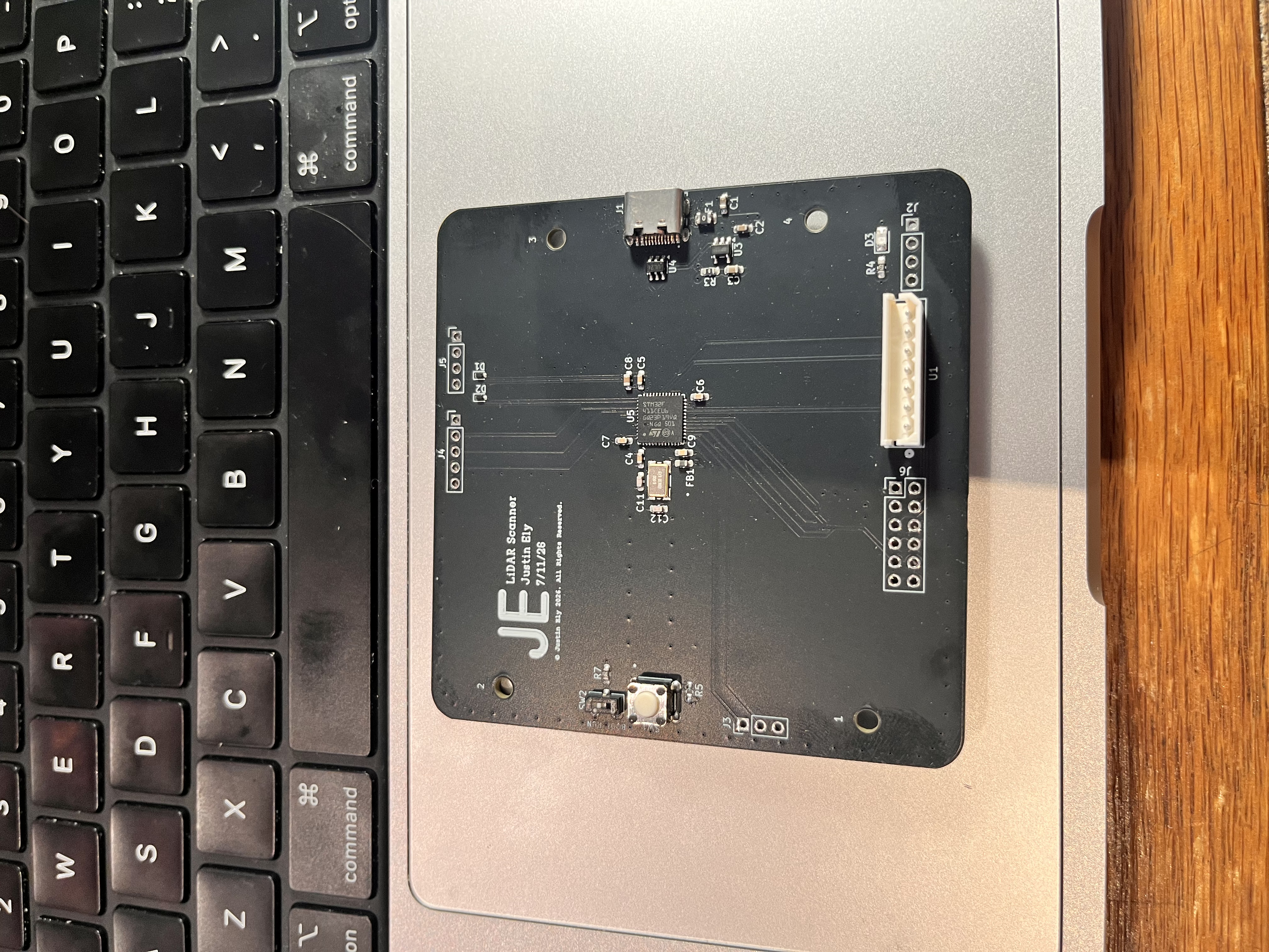
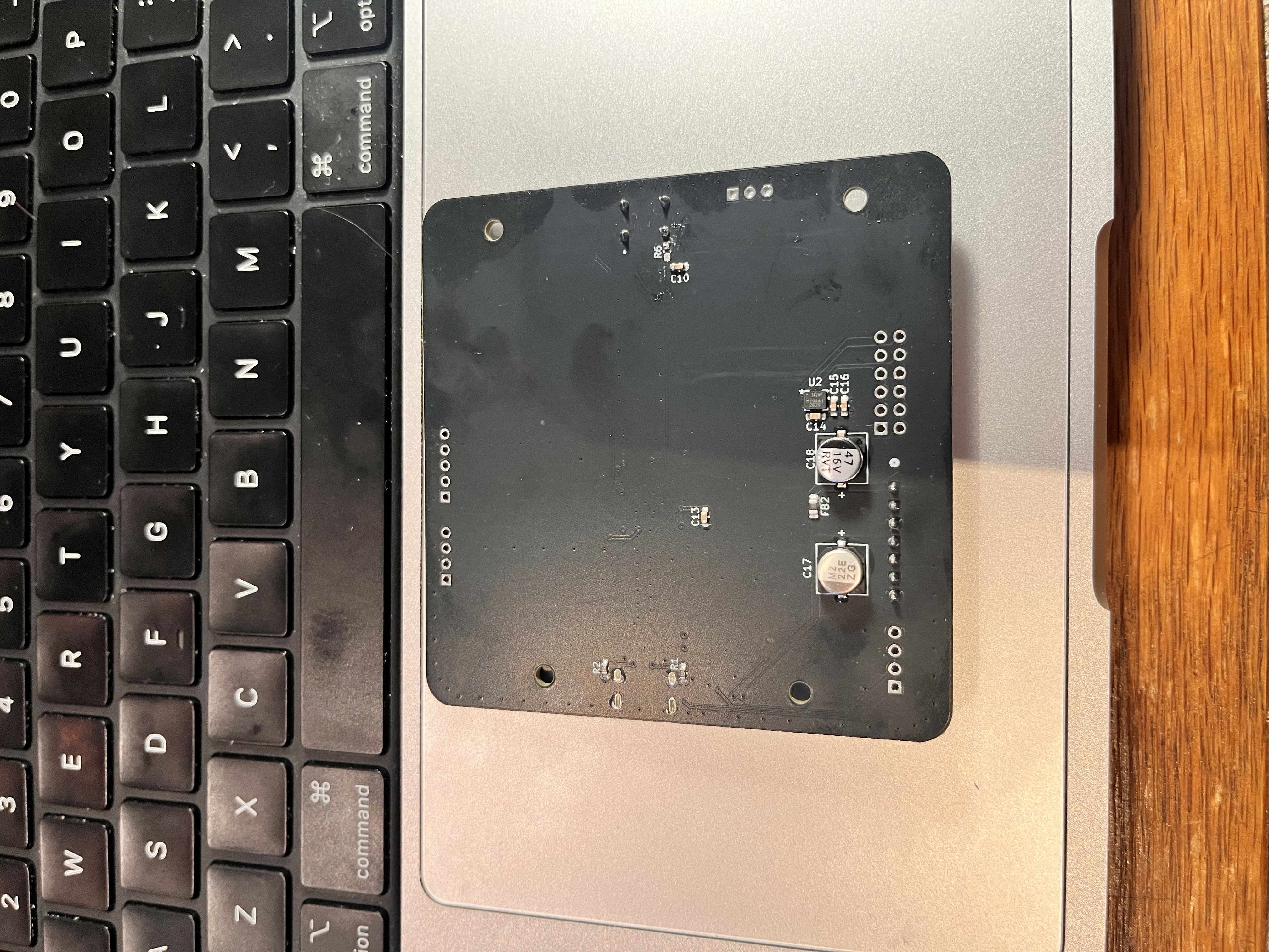
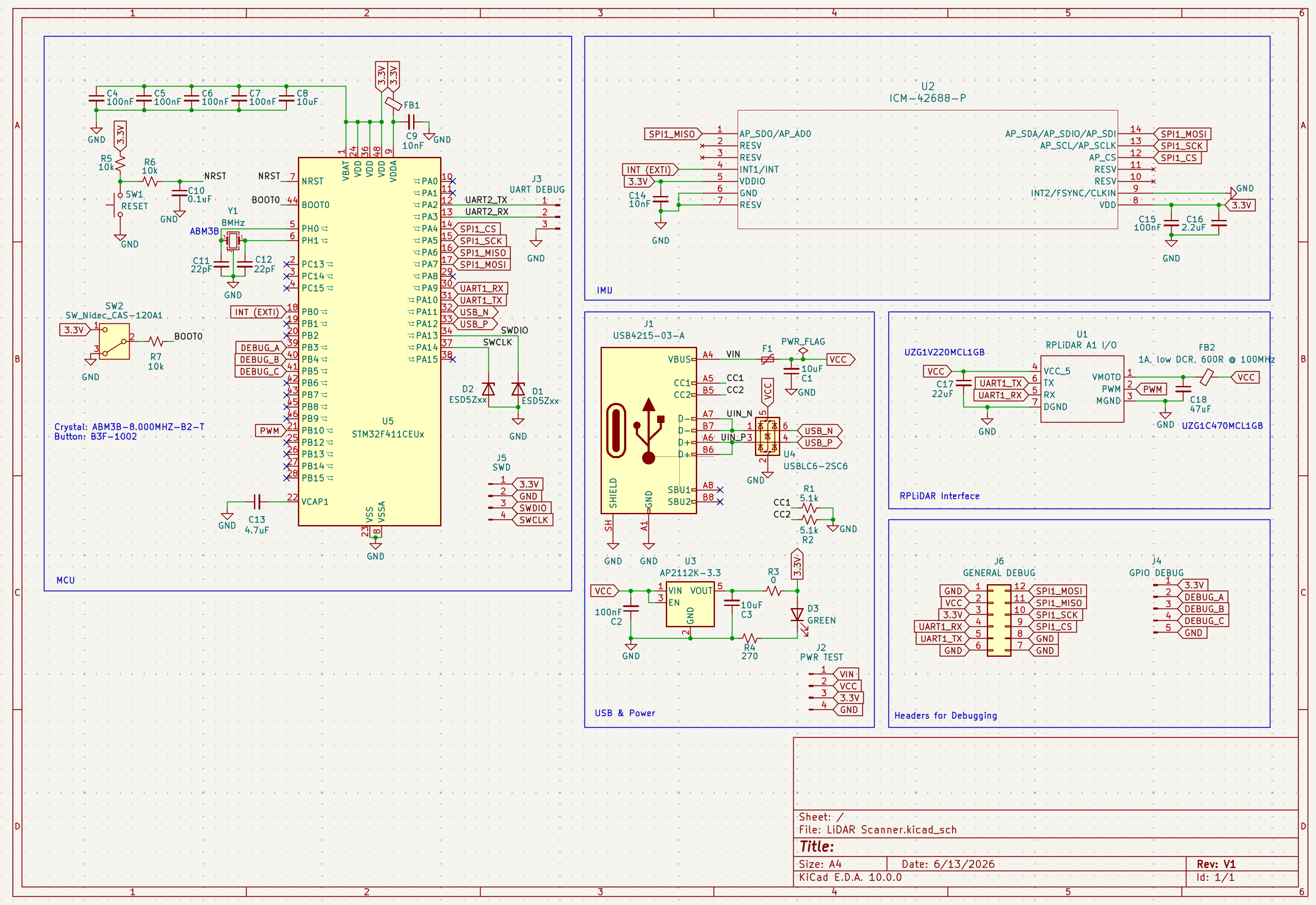
A few notable design decisions:
Gerbers are in:
production/.
NOTE: Designed, tested, and validated by me. Implemented with the help of Claude Code.
Register-level bare-metal C with a 12 KB flash image.
SCAN decoding off USART1 with circular DMA and byte-level resyncFull detail in firmware/README.md,
firmware/HARDWARE.md, and the wire format in
firmware/PROTOCOL.md.
Requires arm-none-eabi-gcc and st-flash (from stlink-tools).
cd firmware
make            # builds build/lidar-imu.bin and prints section sizes
make flash # writes it over SWDNOTE: Designed, tested, and validated by me. Implemented with the help of Claude Code.
Python 3 with NumPy and matplotlib. Reads the USB CDC stream, parses the binary protocol, and renders three views.
cd host
python3 -m pip install -r requirements.txt

python3 -m lidarscan              # live orientation + LiDAR rings
python3 -m lidarscan --cloud      # 3D point cloud, device fixed at the origin
python3 -m lidarscan --cloud-ins  # 3D point cloud with dead-reckoned position
python3 -m lidarscan --sim        # synthetic data, no hardware needed
python3 -m lidarscan --selftest   # 60 self-tests covering the transform chain
--cloud assumes the device only rotates in place. --cloud-ins additionally
double-integrates the accelerometer to estimate translation — see
host/lidarscan/cloud_ins.py for the error budget
and why it drifts. Both write binary PLY that opens in MeshLab, CloudCompare, or
Blender.
Getting these straight is most of the work:
| Frame | Definition |
|---|---|
| Sensor | Raw ICM-42688-P axes. What the Madgwick filter integrates. |
| Body | The board: X forward, Y left, Z up. +Y sensor is forward, −Z sensor is up. |
| Earth | Madgwick's output frame, Z up. Yaw has no absolute reference. |
| LiDAR | The A1's scan plane, related to the body frame by its physical mounting. |
The A1 is a separate module on a cable, so its orientation relative to the PCB
is mechanical and cannot be known from code. --lidar-yaw-deg aligns forward and
--lidar-ccw un-mirrors the sweep; set them once for your mounting.
firmware/          bare-metal STM32F411 firmware
  src/             16 C source files
  include/         headers, incl. board.h — the authoritative pin map
  cmsis/           vendored ARM CMSIS headers
  PROTOCOL.md      normative wire format
  HARDWARE.md      pin map, DMA allocation, link budget
host/
  lidarscan/       Python host application
    protocol.py    framing, CRC, packet encode/decode
    reader.py      serial + simulated sources
    viz.py         orientation and ring views
    cloud.py       3D reconstruction, rotation only
    cloud_ins.py   3D reconstruction with dead reckoning
production/        gerbers, drill, pick-and-place
docs/images/       photos and screenshots for this README
*.kicad_* schematic and PCB sourceWorking end to end: the board is fabricated, assembled, and validated driving the IMU, LiDAR, and USB concurrently at 0.00% measured packet loss and 5.6 rev/s sustained scanning.
Known limits, all understood rather than mysterious:
--cloud-ins position drifts as t². Double integration of a MEMS
accelerometer diverges; zero-velocity updates and bias tracking bound it but
cannot repeal it. Pause frequently while scanning.| Qty | Value | Footprint | References |
|---|---|---|---|
| 6 | 100nF | Capacitor_SMD:C_0603_1608Metric_Pad1.08x0.95mm_HandSolder | C2, C4, C5, C6, C7, C15 |
| 4 | MountingHole_3mm | MountingHole:MountingHole_3mm | 1, 2, 3, 4 |
| 3 | 10uF | Capacitor_SMD:C_0603_1608Metric_Pad1.08x0.95mm_HandSolder | C1, C3, C8 |
| 2 | 10k | Capacitor_SMD:C_0603_1608Metric_Pad1.08x0.95mm_HandSolder | R5, R6 |
| 2 | 10nF | Capacitor_SMD:C_0603_1608Metric_Pad1.08x0.95mm_HandSolder | C9, C14 |
| 2 | 22pF | Capacitor_SMD:C_0603_1608Metric_Pad1.08x0.95mm_HandSolder | C11, C12 |
| 2 | 5.1k | Capacitor_SMD:C_0603_1608Metric_Pad1.08x0.95mm_HandSolder | R1, R2 |
| 2 | ESD5Zxx | Diode_SMD:D_SOD-523 | D1, D2 |
| 1 | 0 | Capacitor_SMD:C_0603_1608Metric_Pad1.08x0.95mm_HandSolder | R3 |
| 1 | 0.1uF | Capacitor_SMD:C_0603_1608Metric_Pad1.08x0.95mm_HandSolder | C10 |
| 1 | 10k | Resistor_SMD:R_0603_1608Metric_Pad0.98x0.95mm_HandSolder | R7 |
| 1 | 1A, low DCR, 600R @ 100MHz | Inductor_SMD:L_0805_2012Metric_Pad1.05x1.20mm_HandSolder | FB2 |
| 1 | 2.2uF | Capacitor_SMD:C_0603_1608Metric_Pad1.08x0.95mm_HandSolder | C16 |
| 1 | 22uF | LiDAR:PCAP_6.3x3-ELECT_NCA-L | C17 |
| 1 | 270 | Capacitor_SMD:C_0603_1608Metric_Pad1.08x0.95mm_HandSolder | R4 |
| 1 | 4.7uF | Capacitor_SMD:C_0603_1608Metric_Pad1.08x0.95mm_HandSolder | C13 |
| 1 | 47uF | LiDAR:PCAP_6.3x3-ELECT_NCA-L | C18 |
| 1 | 8MHz | LiDAR:ABM3B_ABR | Y1 |
| 1 | AP2112K-3.3 | Package_TO_SOT_SMD:SOT-23-5 | U3 |
| 1 | FerriteBead_Small | Inductor_SMD:L_0603_1608Metric_Pad1.05x0.95mm_HandSolder | FB1 |
| 1 | GENERAL DEBUG | Connector_PinHeader_2.54mm:PinHeader_2x06_P2.54mm_Vertical | J6 |
| 1 | GPIO DEBUG | Connector_PinHeader_2.54mm:PinHeader_1x05_P2.54mm_Vertical | J4 |
| 1 | GREEN | LED_SMD:LED_0805_2012Metric_Pad1.15x1.40mm_HandSolder | D3 |
| 1 | ICM-42688-P | LiDAR:LGA14_2P5X3X0P91_TDK | U2 |
| 1 | PWR TEST | Connector_PinHeader_2.54mm:PinHeader_1x04_P2.54mm_Vertical | J2 |
| 1 | Polyfuse_Small | Fuse:Fuse_0805_2012Metric_Pad1.15x1.40mm_HandSolder | F1 |
| 1 | RESET | LiDAR:SW_B3F-1000_OMR | SW1 |
| 1 | STM32F411CEUx | Package_DFN_QFN:QFN-48-1EP_7x7mm_P0.5mm_EP5.6x5.6mm | U5 |
| 1 | SWD | Connector_PinHeader_2.54mm:PinHeader_1x04_P2.54mm_Vertical | J5 |
| 1 | SW_Nidec_CAS-120A1 | Button_Switch_SMD:Nidec_Copal_CAS-120A | SW2 |
| 1 | UART DEBUG | Connector_PinHeader_2.54mm:PinHeader_1x03_P2.54mm_Vertical | J3 |
| 1 | USB4215-03-A | LiDAR:GCT_USB4215-03-A_REVA | J1 |
| 1 | USBLC6-2SC6 | Package_TO_SOT_SMD:SOT-23-6 | U4 |
| 1 | ~ | LiDAR:CONN_22035075_MOL | U1 |
7903555032/AERIS-H743-PCB
A 6-layer STM32H743-based embedded development and flight-control/data-logging PCB designed as a practical hardware-design and PCB-layout project.


desanv01/Flight-Controller-V2
STM32H743 controller: regulated power, signal-only ESC, neutral ArduPilot firmware, manufacturing data and engineering history.


HazzerTheGreat/SPAR
A flight controller for fixed wing UAVs based on the STM32H7 and designed to run betaflight or INAV

klimemam/aiproto_imu
A compact USB-C IMU acquisition board built around the TDK InvenSense ICM-42688-P (high-precision 6-axis MEMS accel + gyro) and an RP2040 microcontroller that streams samples to a PC over USB Type-C as a virtual serial…

QuadFlyController/Electronics
A high-performance, compact, 4-layer flight controller PCB engineered for quadcopters and small UAVs. Built around the STMicroelectronics STM32F411CEU6 MCU, featuring high-rate low-noise motion sensing, barometric…
It measures 82 × 82 mm and has 4 copper layers, 1.58 mm thick.
49 parts, built around the AP2112K-3.3, ICM-42688-P, USBLC6-2SC6 and USB4215-03-A. The full list of its parts is on this page, with links to each part's symbol and footprint where PCBKit's library has them.
From the JEly613/Mini-LiDAR-Board repository on GitHub, at the commit this page was made from: the board is LiDAR Scanner.kicad_pcb and its schematic LiDAR Scanner.kicad_sch. PCBKit opens the board in the browser, with nothing to install.
Its repository states no licence, so its author keeps all rights: ask JEly613 before reusing the design.