
4 layers80.1 × 22.2 mm
M2-smart iot module
antmicro/m2-smart-iot-module
https://antmicro.com/blog/2021/08/open-hardware-smart-m2-radio-module-for-iot/
212 parts30Apache-2.0

 IbrahimOladepo/USB_PCIE_Board
A PCI Express x1 to USB 3.0 expansion card, designed in KiCad. Plugs into a PCIe x1 slot and breaks it out to four USB 3.0 Type-A ports.
USB PCIE Board is an open-source printed circuit board by IbrahimOladepo, from the IbrahimOladepo/USB_PCIE_Board repository on GitHub, published under the GPL-2.0 licence. It is a 4-layer board of 98.2 × 111.5 mm with 175 parts on 125 nets, routed with 1,308 tracks and 580 vias.
It is built around the MX25L4006EM1I-12G, RT5762CHGH6F and UPD720201K8-711-BAC-A, with the SP3011-06UTG, RBR2MM30BTR and 1SS294,LF among its other parts. Its parts include 75 capacitors, 40 resistors, 15 ICs, 15 diodes and 5 connectors. It belongs with the computers and single-board computers boards of this library.


A PCI Express x1 to USB 3.0 expansion card, designed in KiCad. Plugs into a PCIe x1 slot and breaks it out to four USB 3.0 Type-A ports.
The design is built around U1, a Renesas µPD720201 xHCI USB 3.0 host
controller, which bridges the PCIe link to four independent USB 3.0 ports.
| Function | Reference(s) | Part |
|---|---|---|
| PCIe x1 edge connector | J1 | Bus_PCI_Express_x1 |
| USB host controller | U1 | Renesas UPD720201K8-701-BAC-A |
| Controller firmware/config flash | U2 | MX25L4006EM1I-12G (SPI NOR) |
| Controller clock | X1 | 24MHz crystal |
| USB 3.0 Type-A ports | J2–J5 | Molex 48406-0001 |
| Per-port VBUS power switches | U8–U11 | AP2191SG-13 |
| Per-port ESD protection | U12–U15 | SP3011-06UTG |
| Power regulation | U3, U4, U5, U7 | Buck regulators + 3.3V LDO |
Power for the board and its 5V VBUS rails is derived from the PCIe slot's 12V/3.3V supply through an on-board regulation chain.
| Top | Bottom |
|---|---|
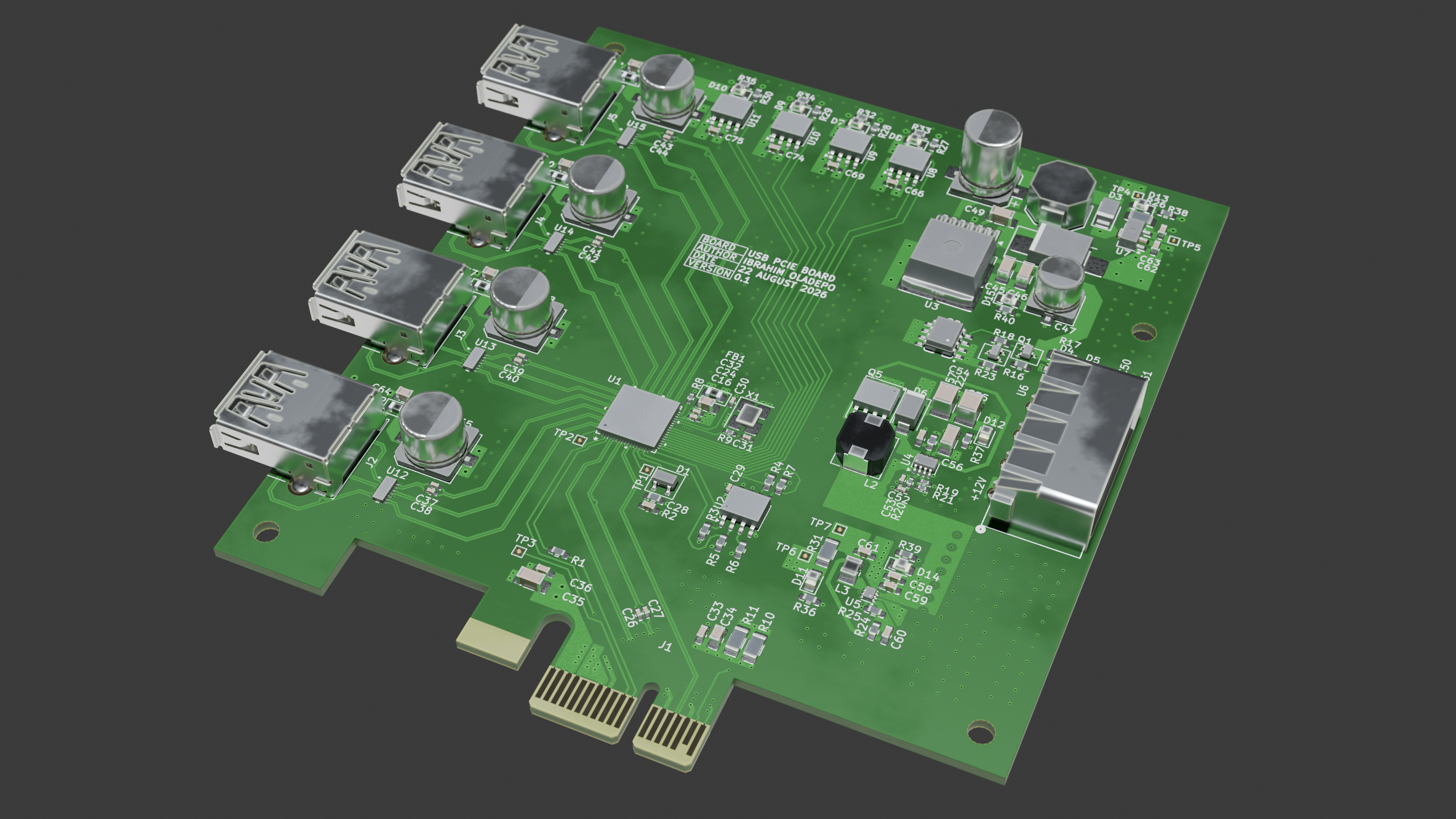 | 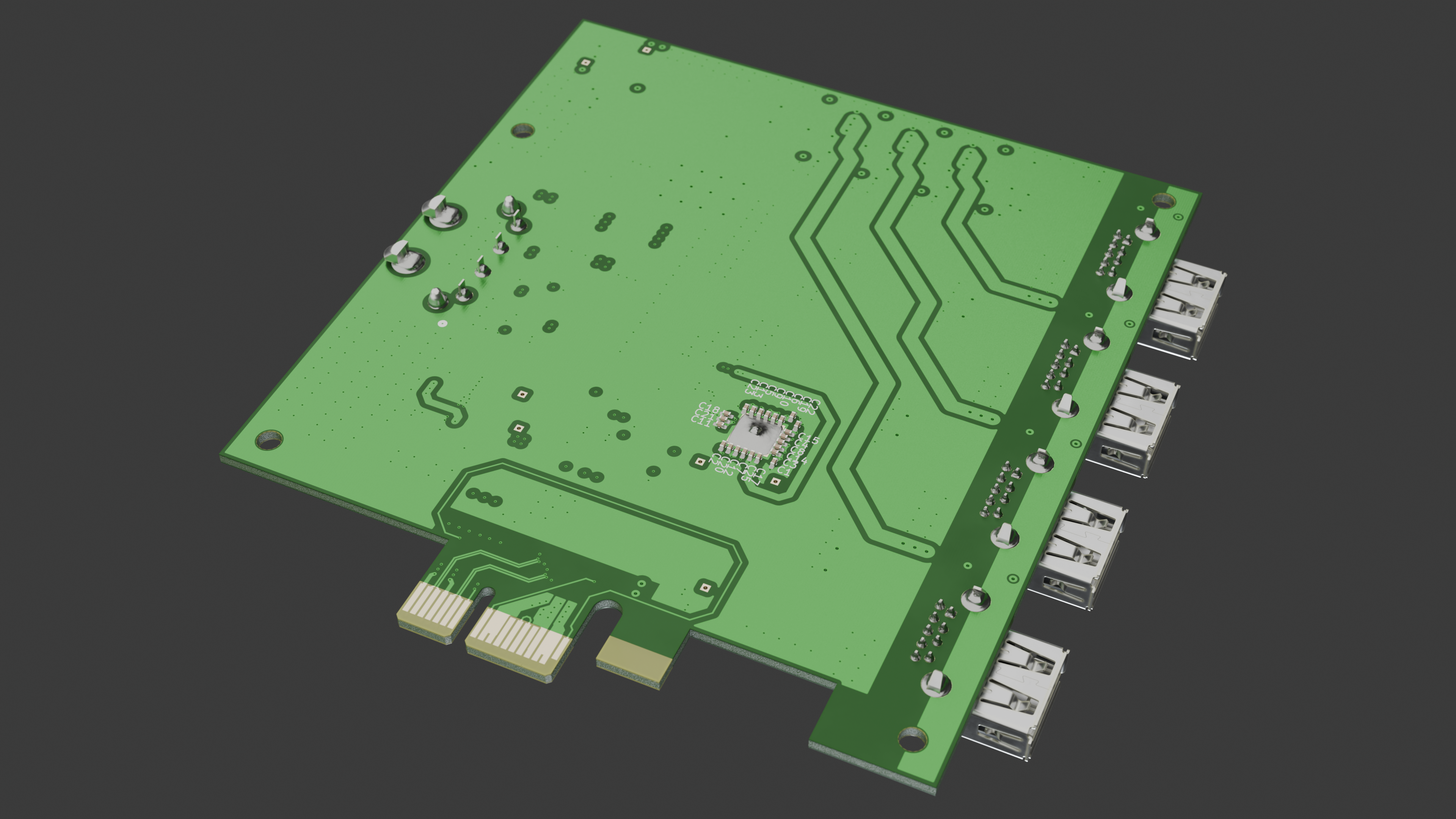 |
| Top | Bottom |
|---|---|
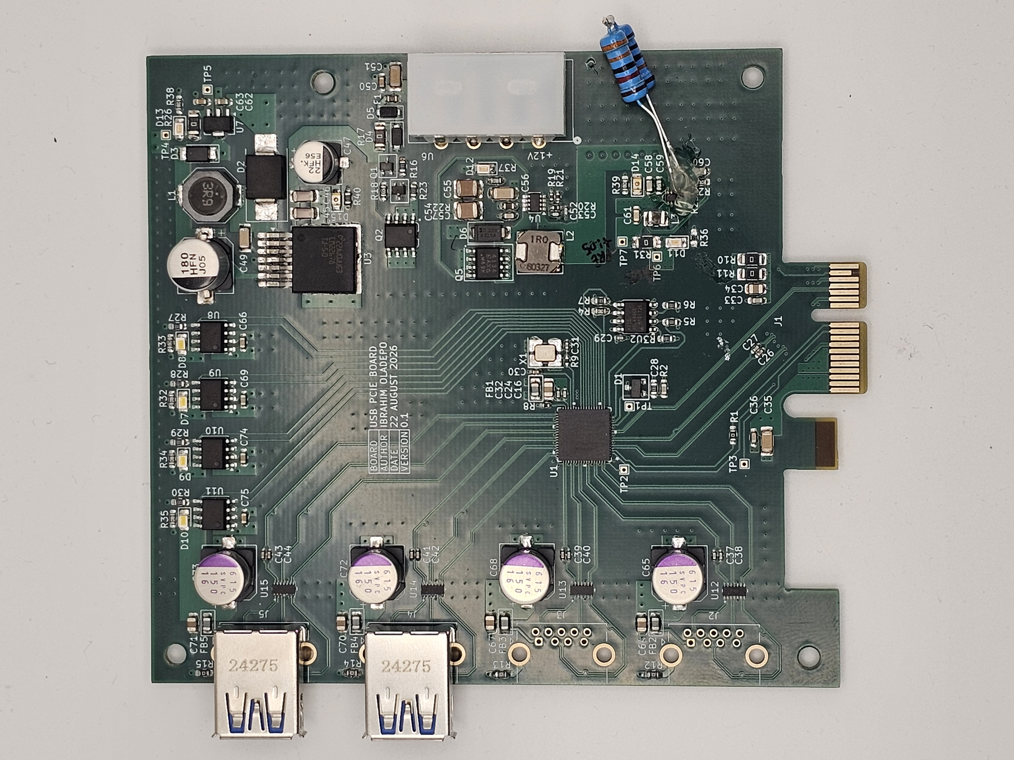 | 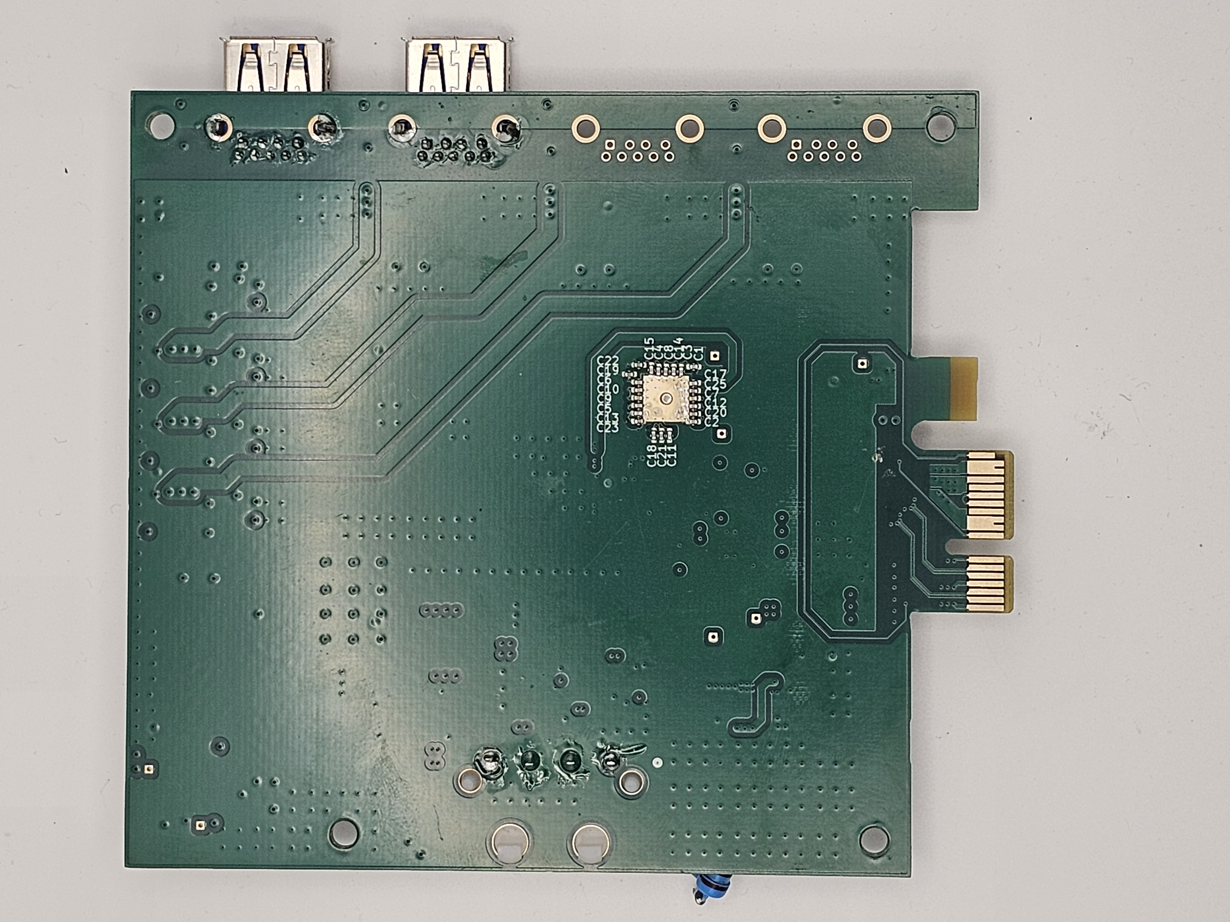 |
The first populated board brought up all rails cleanly except the 1.05V core rail (U5), which came up equal to its input voltage instead of regulating. Bring-up debug (solder-bridge check, continuity check, a U5 swap that didn't help) eventually traced it to the feedback divider: R25 had been sourced as a 133Ω part instead of the 133kΩ the design called for, a unit typo (Ω vs kΩ) that slipped through to the BOM and the order. With R24 (100kΩ, correct) on top and a 133Ω part on the bottom, the feedback node was pulled to nearly 0V, which made the regulator's control loop drive close to 100% duty cycle: output tracking input, exactly as observed.
The through-hole resistors visible in the top-view photo (bottom right, near L3/D14) are the quick fix: a 100kΩ + 33kΩ series pair (133kΩ total) from parts already on hand, soldered in place of the bad R25 so the divider is back at its design value (1.05V output) without waiting on a new part order.
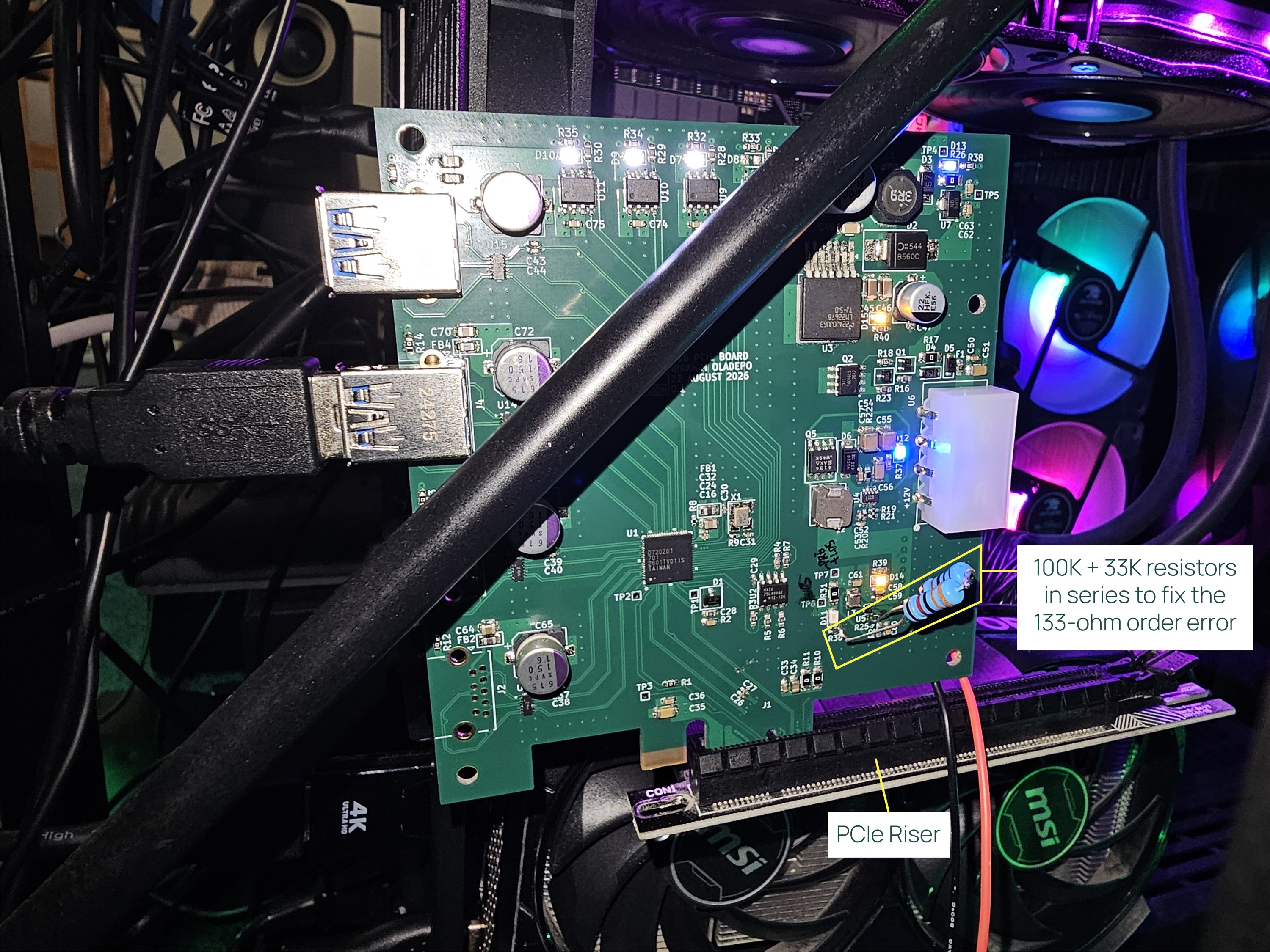
The board is plugged into the PC's PCIe slot through a PCIe riser, for two
reasons: it makes the board easy to probe with a multimeter while powered, and the
case has no room for the board's USB connector placement when seated directly in the
slot. The annotated photo marks the R25 fix and the riser. The original,
un-annotated photo is
2D/Photos/20260920_213102.jpg.
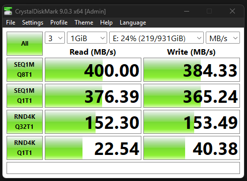
A 1TB SSD connected to one of the board's USB ports, tested with CrystalDiskMark:
| Test | Read (MB/s) | Write (MB/s) |
|---|---|---|
| SEQ1M Q8T1 | 400.00 | 384.33 |
| SEQ1M Q1T1 | 376.39 | 365.24 |
| RND4K Q32T1 | 152.30 | 153.49 |
| RND4K Q1T1 | 22.54 | 40.38 |
SMLMN2BCTT86C with a
forward voltage of about 2.9V, but it is wired across the 1.05V rail, so it can
never turn on. Note that swapping to a lower-Vf colour will not fix this on its own:
a red/yellow/green LED still needs roughly 1.8V or more. Options for v0.2: drive
the LED from +3V3 through a resistor and switch it with a small transistor sensed
from +1V05, or drop the LED and rely on the TP6/TP7 test points.Doc/PCB_Design_Review_Checklist.md for the
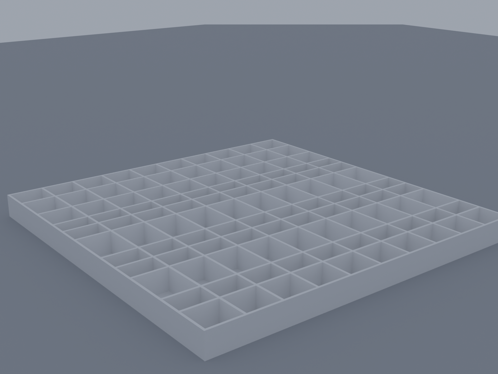
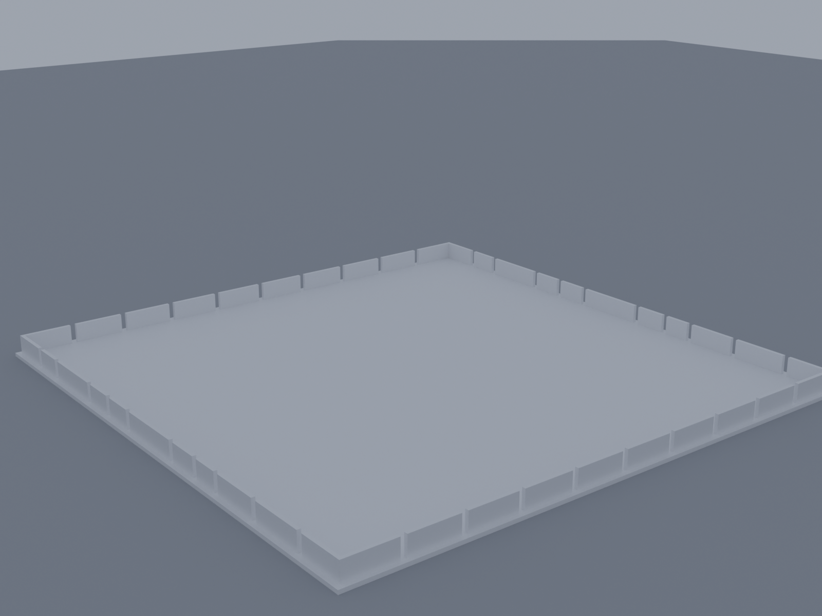
rest of the v0.1 review notes.A 150 x 150 x 10mm box-and-lid pair for sorting the BOM by hand before assembly, one
compartment per distinct part/value. Generated with the
box-stl-generator tool; STL files
are in 3D/Assembly/. Pair it with Doc/Component_Tray_Layout.pdf for a printable,
to-scale cut-out label plus a lookup table mapping each compartment to its BOM entry.
| Box | Lid |
|---|---|
 |  |
Windows Update alone was enough to bring the controller up correctly. In addition, the Renesas USB 3.0 Host Controller Driver (distributed via Dell's driver site) was installed. No manual firmware extraction step was needed on Windows, unlike Linux.
This board uses the Renesas UPD720201K8-701-BAC-A PCIe to USB 3.0 host controller. On
Linux, the xhci-pci-renesas driver requires a firmware blob to bring the controller
online. That firmware is not distributed through the standard linux-firmware package
due to Renesas licensing restrictions, so it has to be installed manually. The steps
below worked on Ubuntu (kernel 7.0.x).
1. Confirm the board is enumerating on PCIe
Before touching firmware, confirm the OS sees the chip at all:
lspci -d 1912:If nothing shows up, this is a hardware bring-up issue (power sequencing, REFCLK/PERST#
timing, card edge connector, or PCIe slot lane availability), not a firmware issue.
Check sudo dmesg | grep -iE "pci|xhci" around boot time for enumeration messages
before proceeding.
Once the chip enumerates correctly, you'll see something like:
xhci-pci-renesas 0000:01:00.0: probe with driver xhci-pci-renesas failed with error -2The -2 (ENOENT) confirms the driver bound successfully but could not find the
firmware file.
2. Get the firmware
The linux-firmware package does not ship renesas_usb_fw.mem for this chip family.
Use the community-maintained mirror instead, which repackages the firmware extracted
from Renesas's official Windows update tool along with checksums:
cd /tmp
wget https://github.com/chunkeey/renesas-fw/raw/master/USB3-201-202-FW-20120615.zip
wget https://github.com/chunkeey/renesas-fw/raw/master/SHA256SUMS
sha256sum -c SHA256SUMS 2>/dev/null | grep -i ok
unzip USB3-201-202-FW-20120615.zip -d renesas-fw-extracted
This covers both the uPD720201 and uPD720202 with a single combined firmware image:
K2013080.mem.
3. Install the firmware
sudo cp /tmp/renesas-fw-extracted/USB3-201-202-FW-20120615/K2013080.mem /lib/firmware/renesas_usb_fw.mem
file /lib/firmware/renesas_usb_fw.mem   # should report "data", not ASCII/HTML
sudo update-initramfs -u
sudo reboot
4. Verify
sudo dmesg | grep -i renesas
lsusb
Expected output on success:
xhci-pci-renesas 0000:01:00.0: xHCI Host Controller
xhci-pci-renesas 0000:01:00.0: new USB bus registered, assigned bus number 3
xhci-pci-renesas 0000:01:00.0: new USB bus registered, assigned bus number 4
xhci-pci-renesas 0000:01:00.0: Host supports USB 3.0 SuperSpeed
usb 4-1: new SuperSpeed USB device number 2 using xhci-pci-renesas
A device plugged into the hub should now show up in lsusb as a SuperSpeed device on
the new bus.
Notes
linux-firmware, this manual
install step will need to be repeated after a fresh OS install or if /lib/firmware
gets wiped. Consider scripting steps 2 to 3 as a setup script in this repo for future
bring-up.USB_PCIE_Board.kicad_pro / .kicad_pcb / .kicad_sch — main project, board, and schematicUSB_PCIE_BOARD_POWER.kicad_sch — power supply schematic sheetDoc/ — documentation, including a PCB design review checklist and the component
tray layout2D/ — board edge outline drawings (.dxf / .ai), and 2D/Photos/ with photos of
the assembled v0.1 board and its bring-up3D/ — Blender renders and STEP/pcb3d exports of the board; 3D/Assembly/ has the
sorting tray's STL files and rendersbom/ — interactive HTML BOM (ibom.html)production/ — generated fabrication outputs (gerbers, BOM, position files)Actively being worked through a design review pass (DRC cleanup, courtyard/footprint
fixes, silkscreen check) — see Doc/PCB_Design_Review_Checklist.md for the current
punch list.
| Qty | Value | Footprint | References |
|---|---|---|---|
| 19 | 0.1uF | Capacitor_SMD:C_0402_1005Metric_Pad0.74x0.62mm_HandSolder | C18, C19, C20, C21, C22, C23, C24, C25, C26, C27, C29, C37, C38, C39, C40, C41 +3 |
| 17 | 0.01uF | Capacitor_SMD:C_0402_1005Metric_Pad0.74x0.62mm_HandSolder | C1, C2, C3, C4, C5, C6, C7, C8, C10, C11, C12, C13, C14, C15, C16, C17 +1 |
| 12 | 10K | Resistor_SMD:R_0603_1608Metric_Pad0.98x0.95mm_HandSolder | R2, R3, R5, R6, R7, R16, R23, R27, R28, R29, R30, R40 |
| 8 | 1K | Resistor_SMD:R_0603_1608Metric_Pad0.98x0.95mm_HandSolder | R32, R33, R34, R35, R36, R37, R38, R39 |
| 7 | 1uF | Capacitor_SMD:C_0603_1608Metric_Pad1.08x0.95mm_HandSolder | C28, C62, C63, C66, C69, C74, C75 |
| 6 | 10uF | Capacitor_SMD:C_0805_2012Metric_Pad1.18x1.45mm_HandSolder | C32, C34, C64, C67, C70, C71 |
| 5 | 0.1uF | Capacitor_SMD:C_0603_1608Metric_Pad1.08x0.95mm_HandSolder | C33, C36, C50, C57, C59 |
| 5 | 0R | Resistor_SMD:R_1206_3216Metric_Pad1.30x1.75mm_HandSolder | R10, R11, R17, R26, R31 |
| 5 | 0R | Resistor_SMD:R_0603_1608Metric_Pad0.98x0.95mm_HandSolder | R1, R12, R13, R14, R15 |
| 5 | BLM21PG600SN1D | 0_Custom:Ferrite_0805_2012Metric_BigPads | FB1, FB2, FB3, FB4, FB5 |
| 4 | 0484050001 | 0_Custom:USB3_A_Molex_48406-0001_Horizontal_Stacked | J2, J3, J4, J5 |
| 4 | 150uF | Capacitor_SMD:CP_Elec_8x6.9 | C65, C68, C72, C73 |
| 4 | AP2191SG-13 | 0_Custom:HSOP-8-1EP_3.9x4.9mm_P1.27mm_EP2.3x2.3mm | U8, U9, U10, U11 |
| 4 | LED_WH | LED_SMD:LED_0805_2012Metric_Pad1.15x1.40mm_HandSolder | D7, D8, D9, D10 |
| 4 | MountingHole | MountingHole:MountingHole_3.2mm_M3 | H1, H2, H3, H4 |
| 4 | SP3011-06UTG | 0_Custom:SON14_SP3011-06UTG_LTF-M | U12, U13, U14, U15 |
| 4 | TestPoint | TestPoint:TestPoint_THTPad_1.0x1.0mm_Drill0.5mm | TP4, TP5, TP6, TP7 |
| 3 | 10uF | Capacitor_SMD:C_1206_3216Metric_Pad1.33x1.80mm_HandSolder | C35, C51, C56 |
| 3 | 22uF | Capacitor_SMD:C_0603_1608Metric_Pad1.08x0.95mm_HandSolder | C58, C60, C61 |
| 3 | D0.5mm | TestPoint:TestPoint_THTPad_1.0x1.0mm_Drill0.5mm | TP1, TP2, TP3 |
| 3 | LED_BL | LED_SMD:LED_0805_2012Metric_Pad1.15x1.40mm_HandSolder | D11, D12, D13 |
| 2 | 100K | Resistor_SMD:R_0603_1608Metric_Pad0.98x0.95mm_HandSolder | R4, R24 |
| 2 | 100uF | Capacitor_SMD:C_1210_3225Metric_Pad1.33x2.70mm_HandSolder | C54, C55 |
| 2 | 6.8uF | Capacitor_SMD:C_1206_3216Metric_Pad1.33x1.80mm_HandSolder | C45, C46 |
| 2 | 8pF | Capacitor_SMD:C_0402_1005Metric_Pad0.74x0.62mm_HandSolder | C30, C31 |
| 2 | LED_YE | LED_SMD:LED_0805_2012Metric_Pad1.15x1.40mm_HandSolder | D14, D15 |
| 2 | RBR2MM30BTR | Diode_SMD:D_SOD-123F | D4, D5 |
| 1 | 1.5uH | Inductor_SMD:L_1008_2520Metric_Pad1.43x2.20mm_HandSolder | L3 |
| 1 | 1.6K | Resistor_SMD:R_0402_1005Metric_Pad0.72x0.64mm_HandSolder | R8 |
| 1 | 1.8nF | Capacitor_SMD:C_0402_1005Metric_Pad0.74x0.62mm_HandSolder | C52 |
| 1 | 10nF | Capacitor_SMD:C_1206_3216Metric_Pad1.33x1.80mm_HandSolder | C49 |
| 1 | 11K | Resistor_SMD:R_0402_1005Metric_Pad0.72x0.64mm_HandSolder | R19 |
| 1 | 133K | Resistor_SMD:R_0603_1608Metric_Pad0.98x0.95mm_HandSolder | R25 |
| 1 | 17.4K | Resistor_SMD:R_0402_1005Metric_Pad0.72x0.64mm_HandSolder | R20 |
| 1 | 180uF | Capacitor_SMD:CP_Elec_8x10.5 | C48 |
| 1 | 1M | Resistor_SMD:R_0603_1608Metric_Pad0.98x0.95mm_HandSolder | R22 |
| 1 | 1SS294,LF | PCM_Package_TO_SOT_SMD_AKL:SC-59 | D1 |
| 1 | 1uH | 0_Custom:IND_SPM6530T-1R0M120 | L2 |
| 1 | 22uF | Capacitor_SMD:CP_Elec_6.3x5.9 | C47 |
| 1 | 2SA1576AT106R | 0_Custom:SOT-323_SC-70 | Q1 |
| 1 | 2SC4081T106R | 0_Custom:SOT-323_SC-70 | Q2 |
| 1 | 3.9uH | 0_Custom:IND_BOURNS_SRU8043 | L1 |
| 1 | 32V/3.15A | Fuse:Fuse_0603_1608Metric_Pad1.05x0.95mm_HandSolder | F1 |
| 1 | 34.8K | Resistor_SMD:R_0402_1005Metric_Pad0.72x0.64mm_HandSolder | R21 |
| 1 | 47K | Resistor_SMD:R_0603_1608Metric_Pad0.98x0.95mm_HandSolder | R18 |
| 1 | 47pF | Capacitor_SMD:C_0402_1005Metric_Pad0.74x0.62mm_HandSolder | C53 |
| 1 | 641737-1 | 0_Custom:641737-1_TYC | U6 |
| 1 | 680R | Resistor_SMD:R_0402_1005Metric_Pad0.72x0.64mm_HandSolder | R9 |
| 1 | AP7215-33YG-13 | Package_TO_SOT_SMD:SOT-89-3 | U7 |
| 1 | B320A-13-F | Diode_SMD:D_SMA | D6 |
| 1 | B560C-13-F | Diode_SMD:D_SMC_Handsoldering | D2 |
| 1 | Bus_PCI_Express_x1 | Connector_PCBEdge:BUS_PCIexpress_x1 | J1 |
| 1 | CS14522-24M | Crystal:Crystal_SMD_3225-4Pin_3.2x2.5mm_HandSoldering | X1 |
| 1 | DMT6016LSS-13 | PCM_SparkFun-Semiconductor-Standard:SO-8 | Q4 |
| 1 | LM22678TJ-5.0/NOPB | Package_TO_SOT_SMD:TO-263-7_TabPin8 | U3 |
| 1 | LTC3872ETS8-TRPBF | Package_TO_SOT_SMD:TSOT-23-8 | U4 |
| 1 | MX25L4006EM1I-12G | 0_Custom:HSOP-8-1EP_3.9x4.9mm_P1.27mm_EP2.3x2.3mm_FLASH | U2 |
| 1 | RSX501LAM20TR | Diode_SMD:D_SOD-128 | D3 |
| 1 | RT5762CHGH6F | Package_TO_SOT_SMD:SOT-563 | U5 |
| 1 | SI4134DY-T1-GE3 | 0_Custom:SO-8_3.9x4.9mm_P1.27mm | Q5 |
| 1 | UPD720201K8-711-BAC-A | 0_Custom:QFN68_8X8_REN-M_Hand_Soldering | U1 |
antmicro/m2-smart-iot-module
https://antmicro.com/blog/2021/08/open-hardware-smart-m2-radio-module-for-iot/

IITB-Rocket-Team-Avionics/Ember
Experimental Flight Computer with potential mitigations of previous issues faced by FLYTE and a testbed for new systems.


antmicro/scalenode-cm4-baseboard
Baseboard for Raspberry Pi 4 Compute Module optimized for clustering

LZajmi/Artix-7-FPGA-Dev-Board
This repository contains the design files for the custom Artix-7 XC7A100T-FGG484 FPGA development board. This board is built for high-performance applications such as hardware acceleration, video processing, data…


bryce-builds/PiGarage
Open-source Raspberry Pi power management and audio HAT for automotive head-unit use
It measures 98.2 × 111.5 mm and has 4 copper layers, 1.61 mm thick.
175 parts, built around the MX25L4006EM1I-12G, RT5762CHGH6F, UPD720201K8-711-BAC-A and SP3011-06UTG. The full list of its parts is on this page, with links to each part's symbol and footprint where PCBKit's library has them.
From the IbrahimOladepo/USB_PCIE_Board repository on GitHub, at the commit this page was made from: the board is USB_PCIE_Board.kicad_pcb and its schematic USB_PCIE_BOARD_POWER.kicad_sch. PCBKit opens the board in the browser, with nothing to install.
Its repository publishes it under the GPL-2.0 licence: you may reuse it on that licence's terms (keep the author's notice, and for a copyleft licence share your changes alike).