4 layers120 × 75 mm
Portapack h1
portapack-mayhem/mayhem-firmware
The firmware for the HackRF+PortaPack H1/H2/H4/H4M
111 parts5.5kGPL-3.0

 Harshad-vali/QWIIC-SWITCH-PROJECT
"Qwiic-compatible I2C power switch module using PCA9536 GPIO expander — KiCad schematic, PCB layout, and BOM."
Power switch is an open-source printed circuit board by Harshad-vali, from the Harshad-vali/QWIIC-SWITCH-PROJECT repository on GitHub. It is a 2-layer board of 30 × 24 mm with 26 parts on 17 nets, routed with 133 tracks and 26 vias.
It is built around the 74HC1G04GW and PCA9306D. Its parts include 8 resistors, 3 capacitors, 3 ICs, 2 diodes and 2 connectors.


A compact, Qwiic-compatible power switch module built around an I2C GPIO expander, designed for easy integration into modular sensor/electronics setups without extra wiring or a microcontroller doing the switching directly.

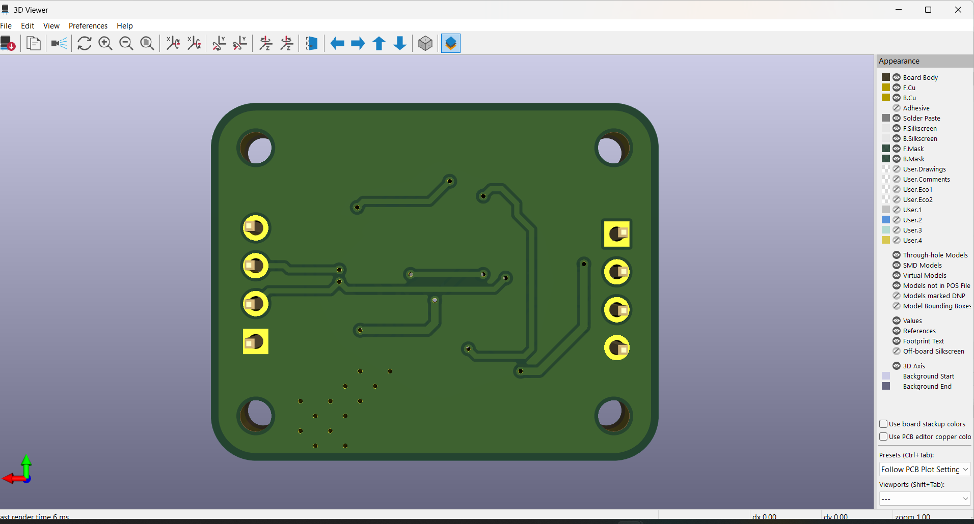
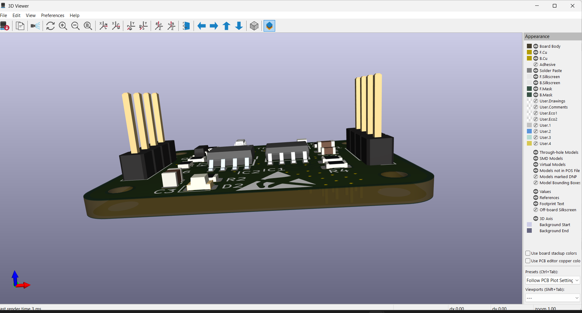
This board lets a host microcontroller switch power to a downstream load over I2C, using a GPIO expander instead of dedicated GPIO pins. It's designed to snap into the Qwiic ecosystem, so it can be daisy-chained with other Qwiic boards with no soldering.
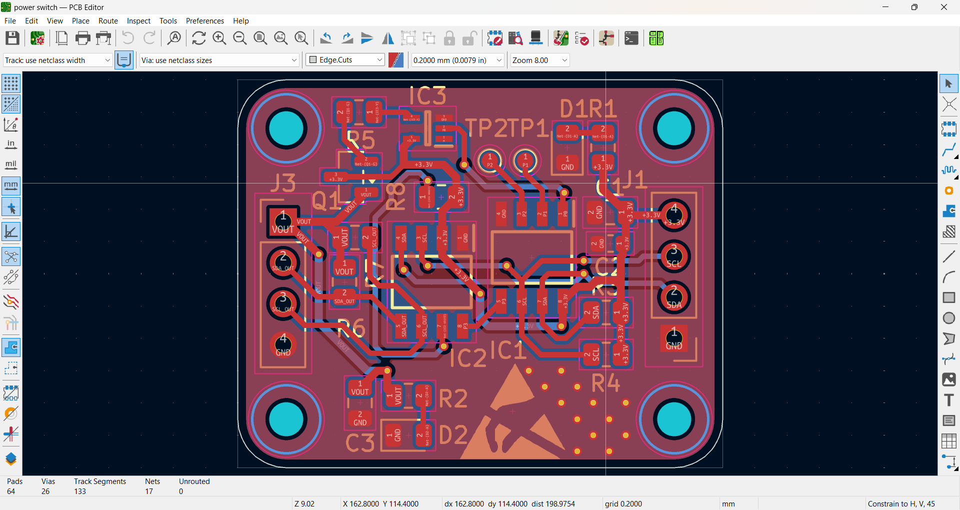
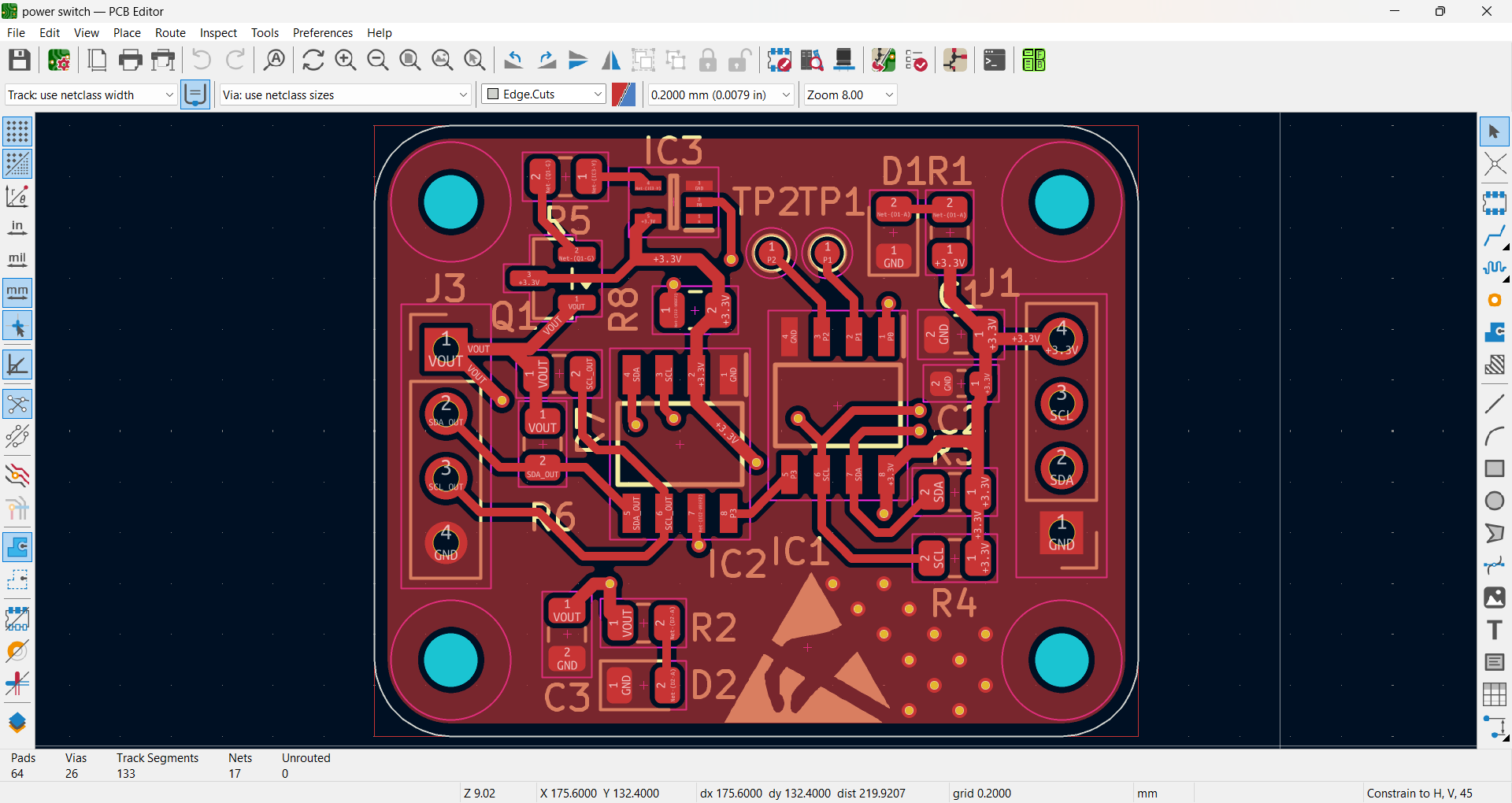
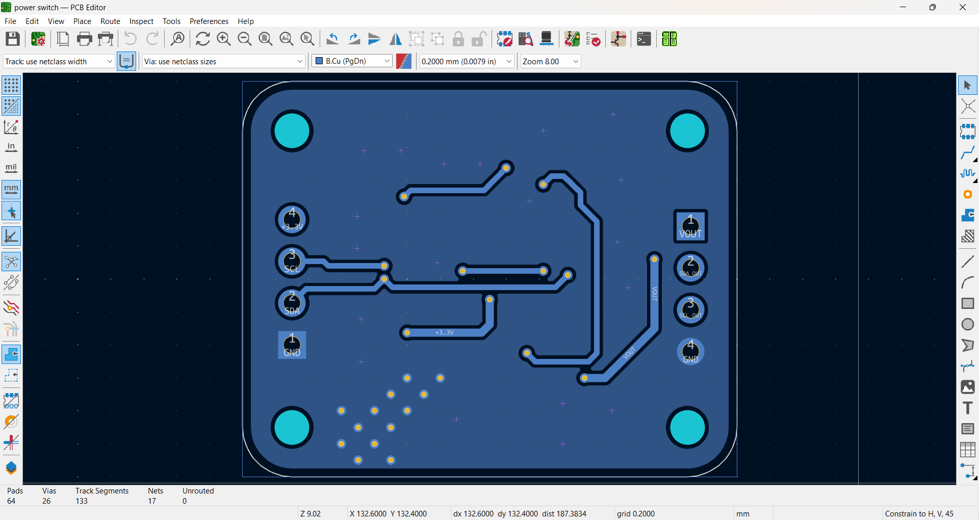
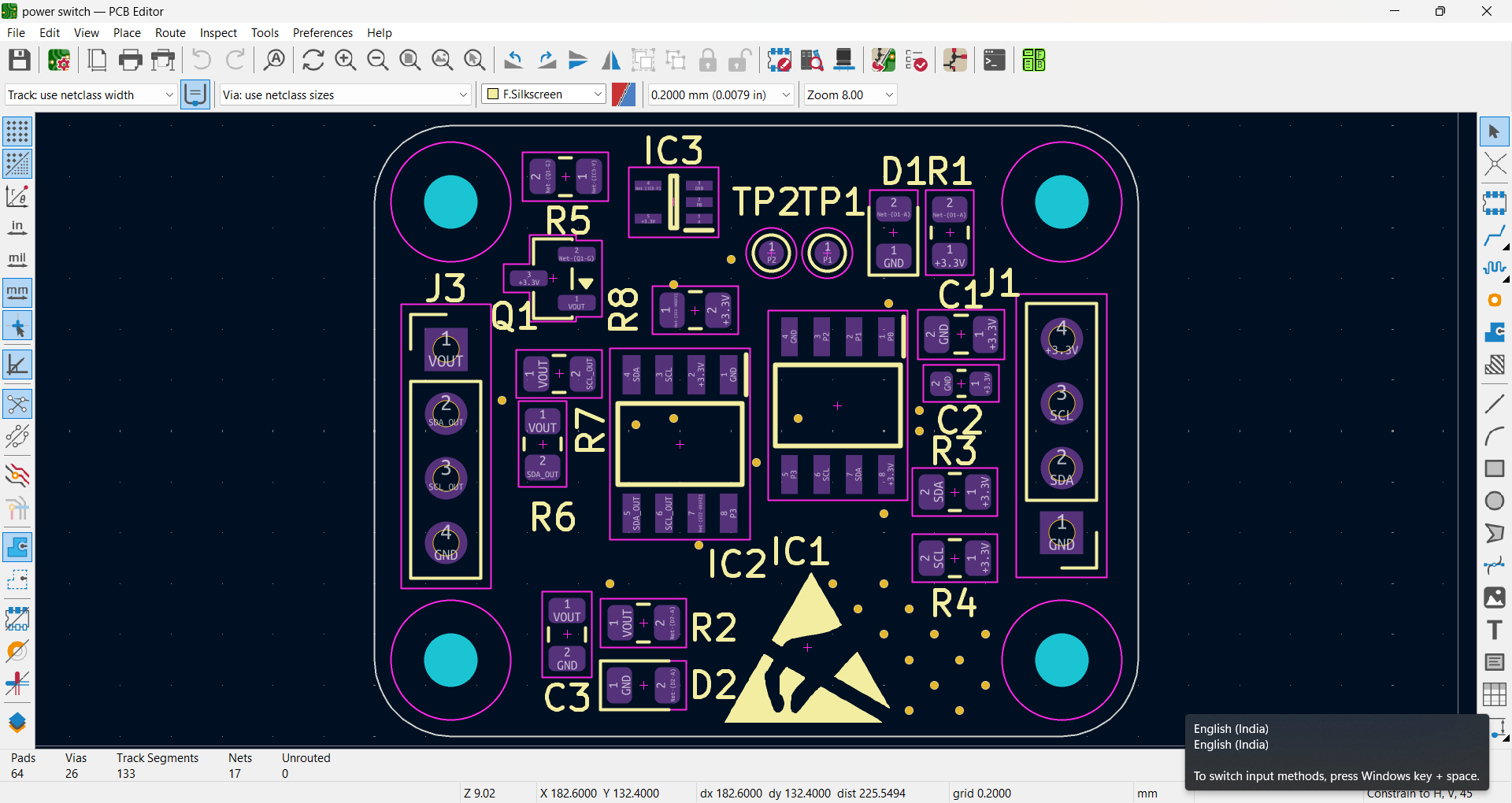
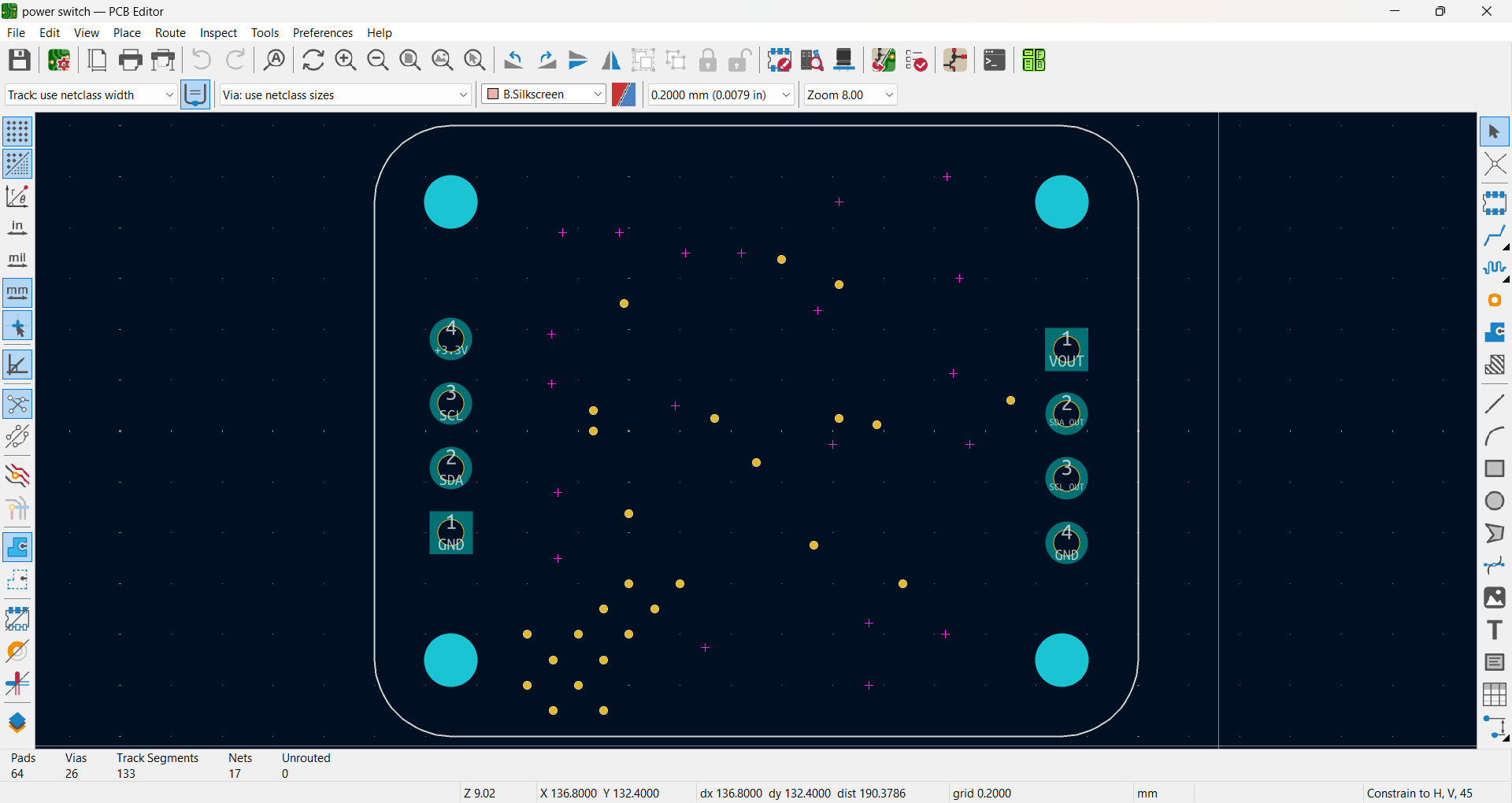

Full schematic PDF: Qwiic_Power_Switch_Schematic_v10.pdf
power switch.kicad_sch / power switch.kicad_pcb / power switch.kicad_pro — full KiCad projectQwiic_Power_Switch_Schematic_v10 (1).pdf — full schematic3D front layer.png, 3D back layer.png, 3D side view.png — 3D rendersfront cu layer.png, back cu layer.png, all cu layers.png — copper layer viewsfront assemble layer.png, back assemble layer.png — assembly drawingsschematic.png — schematic preview imagepower switch proj 3 main bom.xlsx — bill of materials with supplier part numbersPart of a PCB design training program (SUREPROED). Designed and routed independently as part of the coursework.
| Qty | Value | Footprint | References |
|---|---|---|---|
| 4 | 2.2K | Resistor_SMD:R_0805_2012Metric | R3, R4, R6, R7 |
| 4 | MountingHole | MountingHole:MountingHole_2.1mm | H1, H2, H3, H4 |
| 2 | 0.1uF | Capacitor_SMD:C_0805_2012Metric | C1, C3 |
| 2 | 1K | Resistor_SMD:R_0805_2012Metric | R1, R5 |
| 2 | Conn_01x04_Pin | Connector_PinHeader_2.54mm:PinHeader_1x04_P2.54mm_Vertical | J1, J3 |
| 2 | TestPoint | TestPoint:TestPoint_Pad_D1.0mm | TP1, TP2 |
| 1 | 10uF | Capacitor_SMD:C_0603_1608Metric | C2 |
| 1 | 200K | Resistor_SMD:R_0805_2012Metric | R8 |
| 1 | 470 | Resistor_SMD:R_0805_2012Metric | R2 |
| 1 | 74HC1G04GW | usb type c:U1G1 NEW | IC3 |
| 1 | GREEN | LED_SMD:LED_0805_2012Metric | D2 |
| 1 | PCA9306 | usb type c:PCA9306 | IC2 |
| 1 | PCA9536DR | usb type c:PCA9536 | IC1 |
| 1 | PMOS | Package_TO_SOT_SMD:SOT-23 | Q1 |
| 1 | RED | LED_SMD:LED_0805_2012Metric | D1 |
The 25 most common of 26 parts.
portapack-mayhem/mayhem-firmware
The firmware for the HackRF+PortaPack H1/H2/H4/H4M


jdexyz/SimpleAirQualitySensor
A simple air quality sensor using the Adafruit MagTag e-ink display

xenbedded/pixel-c-support
Support hardware and software for running custom code on the Google Pixel C.


juliancoy/zynqPCB
An 8-layer board in Kicad built upon Xilinx Zynq Chip. Includes sound output, HDMI, DDR3, and Arduino Uno style header for screen connection

It measures 30 × 24 mm and has 2 copper layers, 1.6 mm thick.
26 parts, built around the 74HC1G04GW and PCA9306D. The full list of its parts is on this page, with links to each part's symbol and footprint where PCBKit's library has them.
From the Harshad-vali/QWIIC-SWITCH-PROJECT repository on GitHub, at the commit this page was made from: the board is power switch.kicad_pcb and its schematic power switch.kicad_sch. PCBKit opens the board in the browser, with nothing to install.
Its repository states no licence, so its author keeps all rights: ask Harshad-vali before reusing the design.