
2 layers40 × 30 mm
Esphome xiao base
0rax/esphome-xiao-base
XIAO base board PCB & configuration for ESPHome based sensors.
10 parts5CERN-OHL-S-2.0
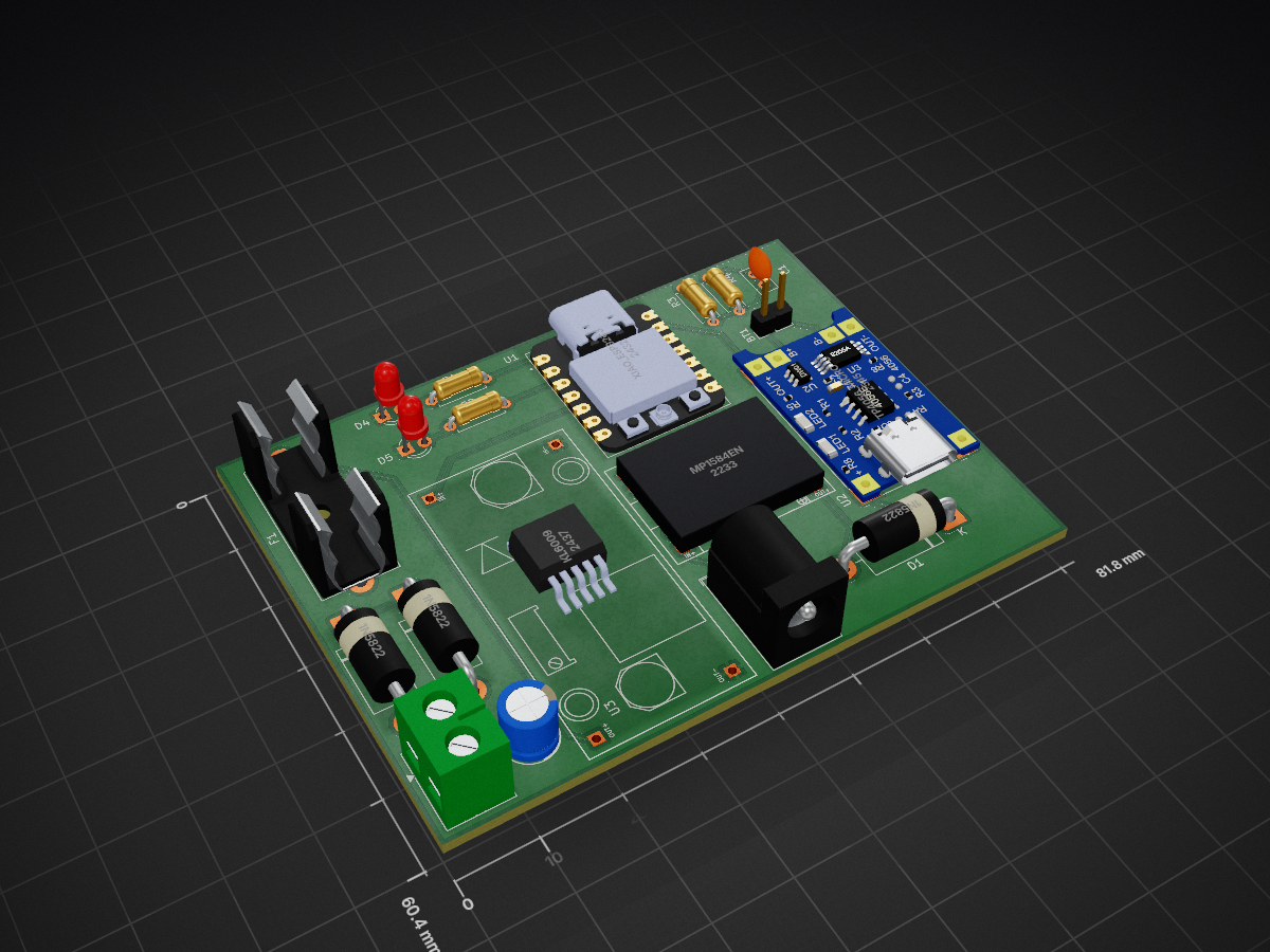
A custom PCB uninterruptible power supply and network diagnostic node using ESP32-C3.
WIFI UPS is an open-source printed circuit board by HarshBotre, from the HarshBotre/IoT-Enabled-WiFi-Router-UPS repository on GitHub. It is a 4-layer board of 81.8 × 60.4 mm with 19 parts on 26 nets, routed with 56 tracks and 0 vias.
It is built around the MP1584EN and XIAO ESP32C3. Its parts include 5 diodes, 4 resistors, 4 ICs, 2 capacitors and 2 connectors. It belongs with the radio and wireless and power boards and the ESP32 and RISC-V boards of this library.
A custom 2-layer PCB designed to provide seamless battery backup for a 12V WiFi router, featuring an onboard ESP32-C3 microcontroller for live network health diagnostics and battery telemetry.
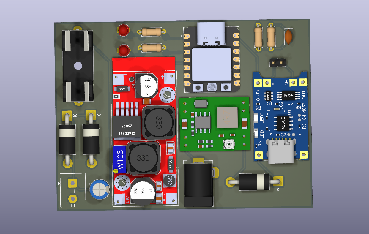
Standard router UPS devices blindly supply power. When the internet drops, users cannot tell if the ISP went down or if the local router lost power. This project solves that by maintaining power while actively pinging external DNS servers to log true ISP outages.
8.8.8.8 to track latency, jitter, and packet loss./Hardware: KiCad schematic, PCB layout, and manufacturing Gerbers./Firmware: C++ logic for the ESP32-C3 network and battery telemetry./Docs: Schematic PDFs and visual assets.| Qty | Value | Footprint | References |
|---|---|---|---|
| 3 | 1N5822 | Diode_THT:D_DO-201AD_P15.24mm_Horizontal | D1, D2, D3 |
| 2 | 220 | Resistor_THT:R_Axial_DIN0207_L6.3mm_D2.5mm_P7.62mm_Horizontal | R1, R2 |
| 2 | LED | LED_THT:LED_D3.0mm | D4, D5 |
| 1 | 100 | Resistor_THT:R_Axial_DIN0207_L6.3mm_D2.5mm_P7.62mm_Horizontal | R3 |
| 1 | 100 | Capacitor_THT:C_Disc_D5.0mm_W2.5mm_P2.50mm | C1 |
| 1 | 33 | Resistor_THT:R_Axial_DIN0207_L6.3mm_D2.5mm_P7.62mm_Horizontal | R4 |
| 1 | 470 C_Polarized | Capacitor_THT:CP_Radial_D6.3mm_P2.50mm | C2 |
| 1 | Battery | Connector_PinHeader_2.54mm:PinHeader_1x02_P2.54mm_Vertical | BT1 |
| 1 | F Barrel-Jack | Connector_BarrelJack:BarrelJack_Horizontal | J1 |
| 1 | Fuse | Fuse:Fuseholder_Cylinder-5x20mm_Schurter_0031_8201_Horizontal_Open | F1 |
| 1 | KL6009 | misc_footprints:XL6009_module | U3 |
| 1 | MP1584EN | misc_footprints:MP1584_buck_module | U4 |
| 1 | Screw_Terminal_01x02 | TerminalBlock:TerminalBlock_MaiXu_MX126-5.0-02P_1x02_P5.00mm | J2 |
| 1 | TP4056_MICRO-USB_CHARGER_-_1A | TP4056_MICRO-USB_CHARGER_-_1A:MODULE_TP4056_MICRO-USB_CHARGER_-_1A | U2 |
| 1 | XIAO_ESP32C3 | XIAO_ESP32C3:MODULE_XIAO_ESP32C3 | U1 |
0rax/esphome-xiao-base
XIAO base board PCB & configuration for ESPHome based sensors.


aayu0-0/SEEED-RS485-Extension-Board-reverse-engineering-project
SEEED RS485 Extension Board reverse-engineering project

AID-IOT/IOT-Memento-Design
A keepsake PCB built at the AICTE IDEA Lab, Poornima College of Engineering. It is a working board as well as a memento: a Seeed XIAO ESP32C3 drives four WS2812B LEDs and reads a BMP280 pressure/temperature sensor, and…

It measures 81.8 × 60.4 mm and has 4 copper layers, 1.6 mm thick.
19 parts, built around the MP1584EN and XIAO ESP32C3. The full list of its parts is on this page, with links to each part's symbol and footprint where PCBKit's library has them.
From the HarshBotre/IoT-Enabled-WiFi-Router-UPS repository on GitHub, at the commit this page was made from: the board is Hardware/WIFI UPS.kicad_pcb and its schematic Hardware/WIFI UPS.kicad_sch. PCBKit opens the board in the browser, with nothing to install.
Its repository states no licence, so its author keeps all rights: ask HarshBotre before reusing the design.