




2 layers308.7 × 241.8 mm
OTTOtact
cester-ino/OTTO-hardware
those specs refer to the tactile buttons version, but a led backlight button version is in the works too.
229 parts49GPL-3.0

 Hang020713/USB-C-Regulator
A compact USB‑C powered boost regulator board based on the MT3608 DC‑DC step‑up converter.
USB C Regulator is an open-source printed circuit board by Hang020713, from the Hang020713/USB-C-Regulator repository on GitHub, published under the MIT licence. It is a 2-layer board of 43.2 × 15.5 mm with 12 parts on 9 nets, routed with 75 tracks and 8 vias.
It is built around the MT3608 and SS34. Its parts include 3 resistors, 2 capacitors, 2 connectors, 1 IC and 1 diode. It belongs with the power boards of this library.
[blocked]
A compact USB‑C powered boost regulator board based on the MT3608 DC‑DC step‑up converter.
This board is designed for small embedded systems, robotics projects, and portable power applications requiring adjustable output voltage from a USB‑C input source.
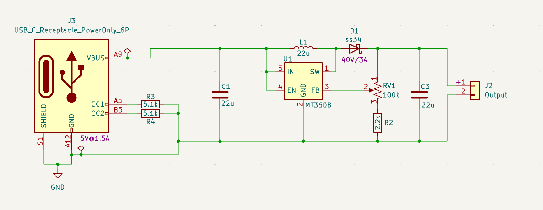
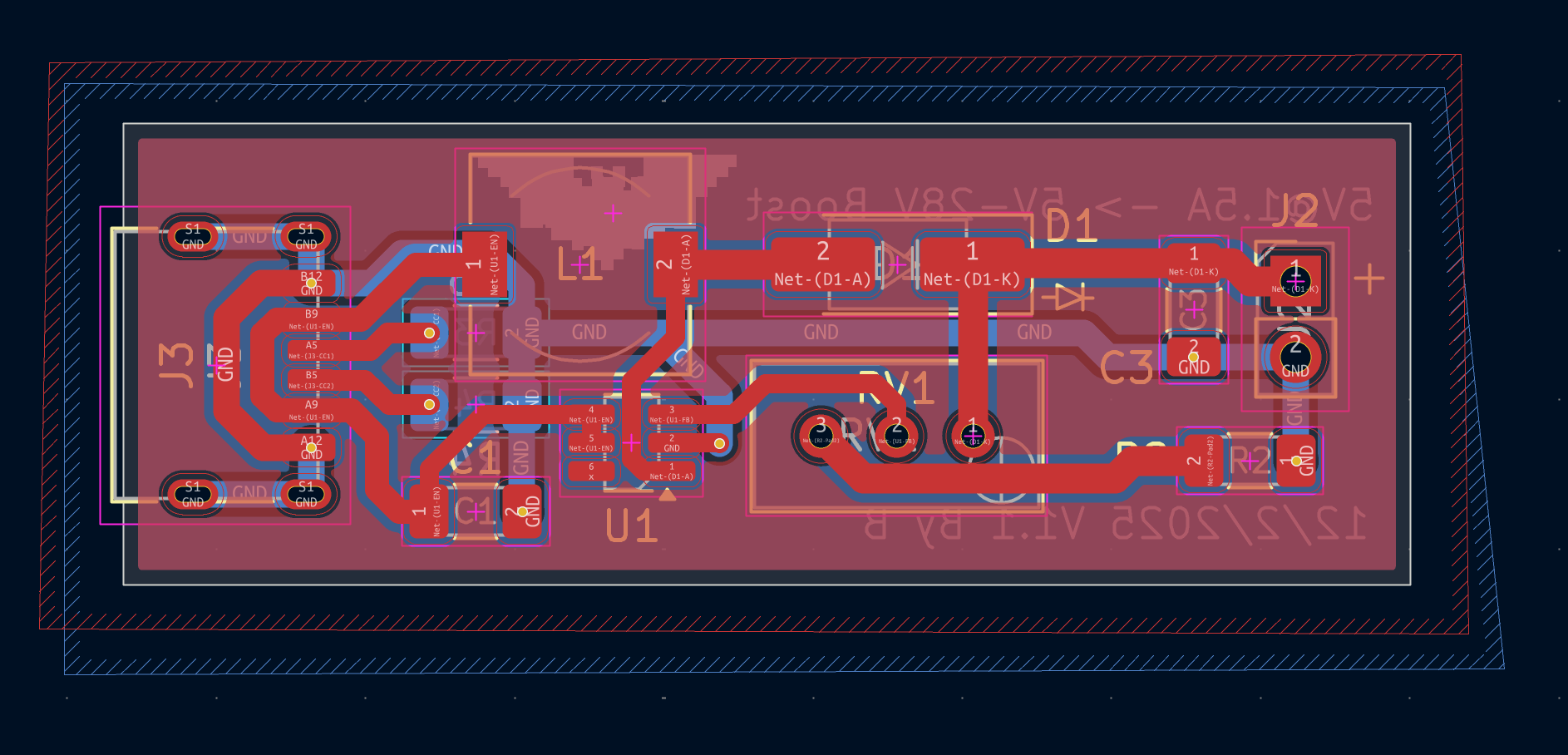
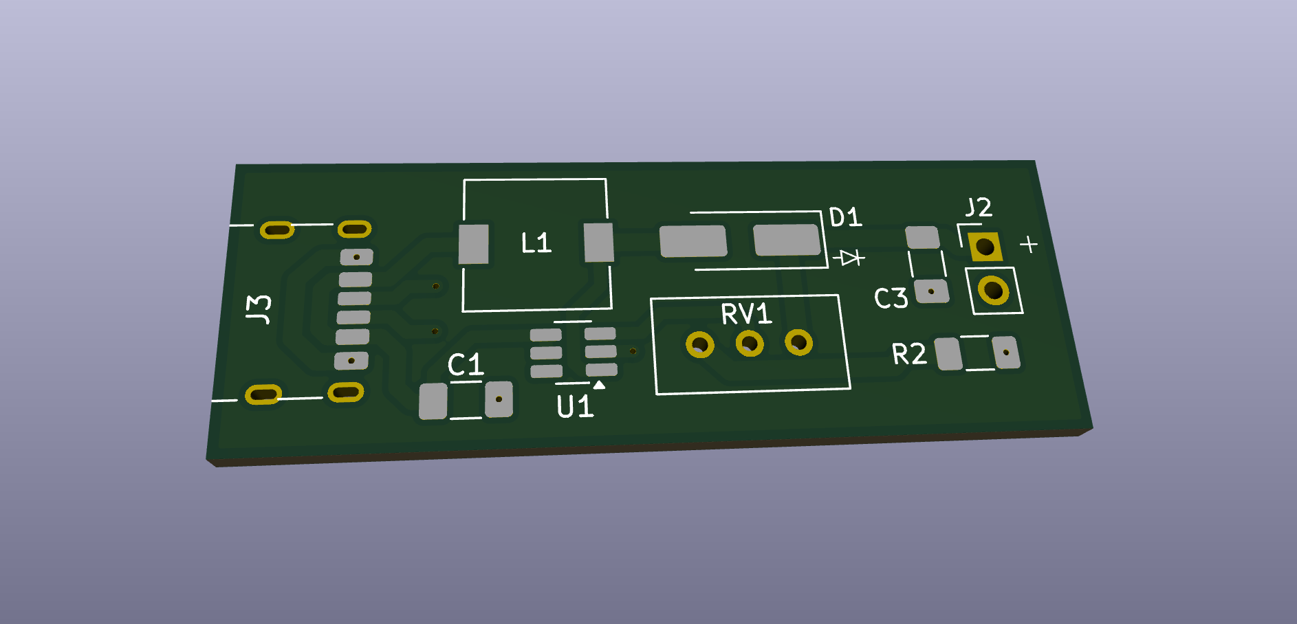
├── USB-C-Regulator.kicad_pcb   # PCB Layout
├── USB-C-Regulator.kicad_pro   # KiCad Project File
├── USB-C-Regulator.kicad_sch   # Schematic
└── README.mdkicad_pcb - PCB Layoutkicad_sch - Schematickicad_pro - KiCad Project Configuration FileRequirements
Open the .kicad_pro file using KiCad 8 to access the full project including schematic and PCB layout.
STM32 Board have below features
⚠️ Always verify output voltage before powering sensitive electronics.
| Reference | Value | Package / Footprint | Qty |
|---|---|---|---|
| C1, C3 | 22 µF Capacitor | 1206 SMD | 2 |
| L1 | 22 µH Inductor | 7.3×7.3 mm SMD | 1 |
| D1 | SS34 Schottky Diode | SMA (SMD) | 1 |
| J2 | 2‑Pin Output Header (2.54 mm) | Through‑hole | 1 |
| J3 | USB‑C Receptacle (Power Only, 6‑Pin) | SMD Type‑C | 1 |
| R2 | 2.2 kΩ Resistor | 1206 SMD | 1 |
| R3, R4 | 5.1 kΩ Resistor | 1206 SMD | 2 |
| RV1 | 100 kΩ Trimmer Potentiometer | Bourns 3296W (THT) | 1 |
| U1 | MT3608 Boost Converter IC | SOT‑23‑6 | 1 |
MIT License
Feel free to use, modify, and distribute.
I'm always interested in collaborating on embedded systems projects, robotics competitions, or autonomous vehicle development!
| Qty | Value | Footprint | References |
|---|---|---|---|
| 2 | 22k | Resistor_SMD:R_1206_3216Metric_Pad1.30x1.75mm_HandSolder | R3, R4 |
| 2 | 22u | Capacitor_SMD:C_1206_3216Metric_Pad1.33x1.80mm_HandSolder | C1, C3 |
| 1 | 100k | Potentiometer_THT:Potentiometer_Bourns_3296W_Vertical | RV1 |
| 1 | 2.2k | Resistor_SMD:R_1206_3216Metric_Pad1.30x1.75mm_HandSolder | R2 |
| 1 | 22u | Inductor_SMD:L_7.3x7.3_H3.5 | L1 |
| 1 | LOGO | LOGO | G*** |
| 1 | MT3608 | Package_TO_SOT_SMD:SOT-23-6_Handsoldering | U1 |
| 1 | Output | Connector_PinHeader_2.54mm:PinHeader_1x02_P2.54mm_Vertical | J2 |
| 1 | USB_C_Receptacle_PowerOnly_6P | Connector_USB:USB_C_Receptacle_HRO_TYPE-C-31-M-17 | J3 |
| 1 | ss34 | Diode_SMD:D_SMA_Handsoldering | D1 |
cester-ino/OTTO-hardware
those specs refer to the tactile buttons version, but a led backlight button version is in the works too.

pcbcupid/Lora-Wireless-Sensor-Network
A wireless sensor network based on Lora and esp32C3. This repo will help you build a complete product from scratch to finish!

Pwnsat/PWNCUBE
PWNCUBE v1.0 is a Cubesat hardware based platform for aerospace cybersecurity research

szbeni/forcegauge
Traning for climbing. Load cell with HX711 and real time plotting,

vitaliy-bobrov/avr-transistor-tester
Component/Transistor tester based on famous AVR Transistor Tester

MAATHES-THILAK-K/ESP32-S3_FLIGHT_CONTROLLER
A custom-designed flight controller based on the ESP32-S3 module, built for compatibility with the esp-fc firmware and Betaflight-like configuration.

denorath-sys/gridnet
Open hardware powerline mesh communication terminal

enwi/PiSupply
Uninterruptable power supply for Raspberry Pi's, which can also power external HDDs
It measures 43.2 × 15.5 mm and has 2 copper layers, 1.6 mm thick.
12 parts, built around the MT3608 and SS34. The full list of its parts is on this page, with links to each part's symbol and footprint where PCBKit's library has them.
From the Hang020713/USB-C-Regulator repository on GitHub, at the commit this page was made from: the board is USB-C-Regulator.kicad_pcb and its schematic USB-C-Regulator.kicad_sch. PCBKit opens the board in the browser, with nothing to install.
Its repository publishes it under the MIT licence: you may reuse it on that licence's terms (keep the author's notice, and for a copyleft licence share your changes alike).