

2 layers64 × 128.5 mm
MiniVCA 1.0
benjiaomodular/MiniVCA
A small footprint LM13700 VCA module for Eurorack modular synth
42 parts31MIT

 HB9UF/SignalSnitch1
An RF detector kit with THT parts
SignalSnitch is an open-source printed circuit board by HB9UF, from the HB9UF/SignalSnitch repository on GitHub. It is a 2-layer board of 87 × 54 mm with 15 parts on 10 nets, routed with 31 tracks and 0 vias.
It is built around the CR2032 and BC559. Its parts include 3 resistors, 2 diodes, 2 transistors and 1 capacitor. It belongs with the radio and wireless boards of this library.
At the Fantasy Basel 2025, we were thrilled to participate with a booth, sharing the space with AMSAT-HB in the section of the Swiss Space Museum. As part of our contribution to this unique blend of science, pop culture, and hands-on experiences, we introduced the SignalSnitch -- a simple, educational RF detector kit designed by Andreas HB9HDF.
The SignalSnitch kit was created specifically for this event to spark interest in amateur radio through a hands-on activity that anyone could enjoy. The kit uses through-hole technology (THT) components to keep assembly straightforward and beginner-friendly, making it ideal for both newcomers and seasoned enthusiasts. Once put together, it lights up an LED when it detects the presence of a nearby RF signal, offering a tangible and satisfying introduction to radio frequency detection.
The concept behind SignalSnitch is not entirely new -- it builds upon a similar kit with SMD parts conceived by Hansjörg HB9DWS and implemented by Matt HB9FRV for the 2019 HAMFEST in Zug.
The response was overwhelmingly positive! We had a fantastic time meeting fellow hobbyists, curious newcomers, and future radio amateurs. We were out of kits long before the fare ended. A heartfelt thank you to everyone who helped make this project possible and to all who stopped by to build their own SignalSnitch. Your enthusiasm made this experience truly memorable.
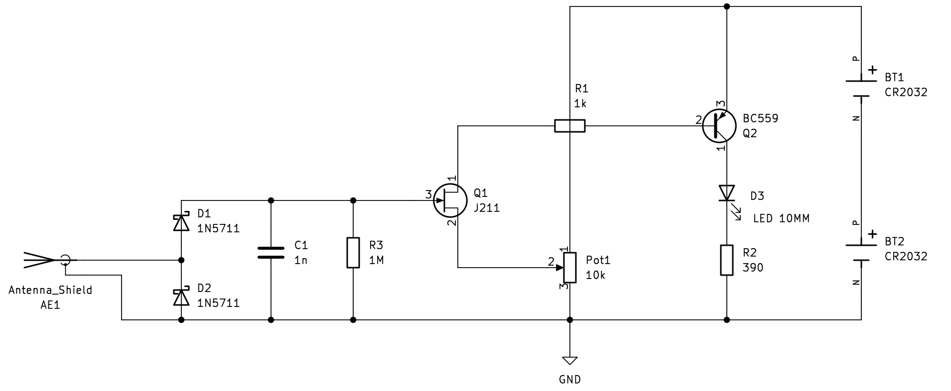
This simple circuit works as follows: The PCB antenna picks up electromagnetic fields, in consequence, AC voltage develops across the antenna terminals. Diodes D1 and D2 rectify this AC voltage to a DC voltage across capacitor C1. This DC voltage activates JFET Q1 which in turn enables Q2. Light is emitted by LED D3 due to the resulting collector current. Bias can be adjusted with Pot1.
The PCB features the schematic on the front side and a QR code for assembly instructions. Components are clearly labeled and assembly is straight forward. See below for images of the board as well as a video of the kit in operation.


| Qty | Value | Footprint | References |
|---|---|---|---|
| 2 | 1N5711 | Diode_THT:D_DO-35_SOD27_P7.62mm_Horizontal | D1, D2 |
| 2 | CR2032 | CoinCellHolder:BAT_1066 | BT1, BT2 |
| 2 | Pin_D1.3mm_L11.0mm | Connector_Pin:Pin_D1.3mm_L11.0mm | Ant -, Ant + |
| 1 | 10k | Potentiometer_THT:Potentiometer_Bourns_3296X_Horizontal | Pot1 10k |
| 1 | 1M | Resistor_THT:R_Axial_DIN0207_L6.3mm_D2.5mm_P7.62mm_Horizontal | R3 1M |
| 1 | 1k | Resistor_THT:R_Axial_DIN0207_L6.3mm_D2.5mm_P10.16mm_Horizontal | R1 1k |
| 1 | 1n | Capacitor_THT:C_Disc_D4.3mm_W1.9mm_P5.00mm | C1 1n |
| 1 | 390 | Resistor_THT:R_Axial_DIN0207_L6.3mm_D2.5mm_P7.62mm_Horizontal | R2 390 |
| 1 | BC559 | Package_TO_SOT_THT:TO-92_Inline_Wide | Q2 BC559 |
| 1 | LED 10MM | LED_THT:LED_D10.0mm | LED |
| 1 | LOGO | LOGO | G*** |
| 1 | TO-92_Inline_Wide | Package_TO_SOT_THT:TO-92_Inline_Wide | Q1 J211 |
benjiaomodular/MiniVCA
A small footprint LM13700 VCA module for Eurorack modular synth

BleepSound/ms20-vcf-double
MS20-VCF clone based on BartonSynth version.


abhayap/SpHEAR
The SpHEAR (Spherical Harmonics Ear) Project is a collection of 3D models and associated code for building, testing and calibrating full surround Ambisonics microphones.

ali5ter/Penfold_VCO
🎛️ R.A. Penfold's VCO design adapted as a Eurorack powered module

pozsarzs/mini_serial_console-hw
Mini serial console with 20x4 LCD, six buttons and three different serial ports


It measures 87 × 54 mm and has 2 copper layers, 1.6 mm thick.
15 parts, built around the CR2032 and BC559. The full list of its parts is on this page, with links to each part's symbol and footprint where PCBKit's library has them.
From the HB9UF/SignalSnitch repository on GitHub, at the commit this page was made from: the board is signal_snitch.kicad_pcb and its schematic signal_snitch.kicad_sch. PCBKit opens the board in the browser, with nothing to install.
Its repository states no licence, so its author keeps all rights: ask HB9UF before reusing the design.