2 layers45 × 172 mm
Ph portable refrigerator v2 hw
Blackcastus/ESP32_A7670
To make it easy for you to get started with GitLab, here's a list of recommended next steps.
188 parts

 Gleb-Vlasov/WeatherStation
WiFi-connected weather station on a custom ESP32 PCB — BME280 sensor, modular display, USB-C. Built from scratch in KiCad.
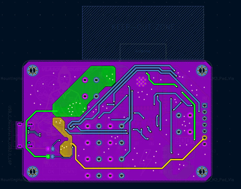
WeatherStation is an open-source printed circuit board by Gleb-Vlasov, from the Gleb-Vlasov/WeatherStation repository on GitHub, published under the MIT licence. It is a 2-layer board of 77.5 × 48 mm with 46 parts on 58 nets, routed with 360 tracks and 137 vias.
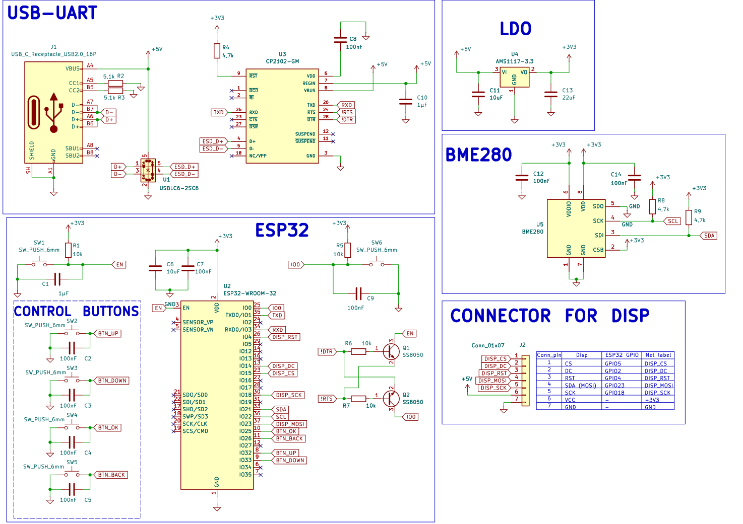
It is built around the ESP32-WROOM-32, BME280 and CP2102-GM, with the AMS1117-3.3, USBLC6-2SC6 and SS8050 among its other parts. Its parts include 14 capacitors, 9 resistors, 6 switches, 5 ICs and 2 transistors. It belongs with the home automation and IoT and radio and wireless boards and the ESP32 boards of this library.


[blocked]
🌐 Language / Язык: 🇬🇧 English • 🇷🇺 Русский
[blocked]
A compact, WiFi-connected weather station built around the ESP32-WROOM-32.
Custom 2-layer PCB designed from scratch in KiCad.
VLASOV INDUSTRIES
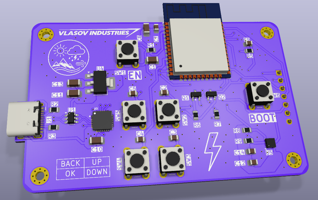





This is a fully custom weather station PCB designed around the ESP32-WROOM-32. Unlike a typical breadboard prototype, every component here sits on a purpose-built board — from the USB-to-UART bridge to the power regulation, sensor interface, and a modular display connector.
The device measures the local environment with an on-board BME280 sensor (temperature, humidity, and barometric pressure) and, thanks to the ESP32's built-in WiFi, can pull live weather data from the internet and display it on an attached screen. Four navigation buttons let you move through screens and menus directly on the device — no computer required after flashing.
Because the heart of the board is a full ESP32 with WiFi, this is far more than a thermometer. It's an open, programmable platform: you can extend it to show forecasts, multiple cities, air-quality indices, sunrise/sunset times, alerts — essentially anything available from a weather API — and control all of it with the four on-board buttons.
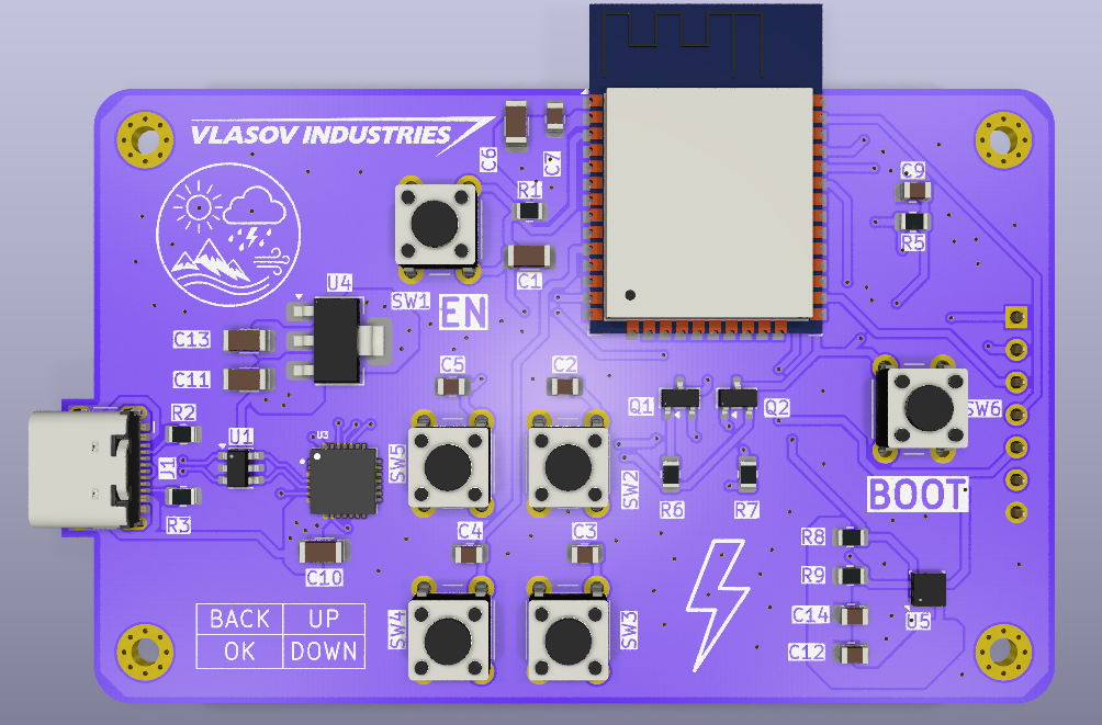
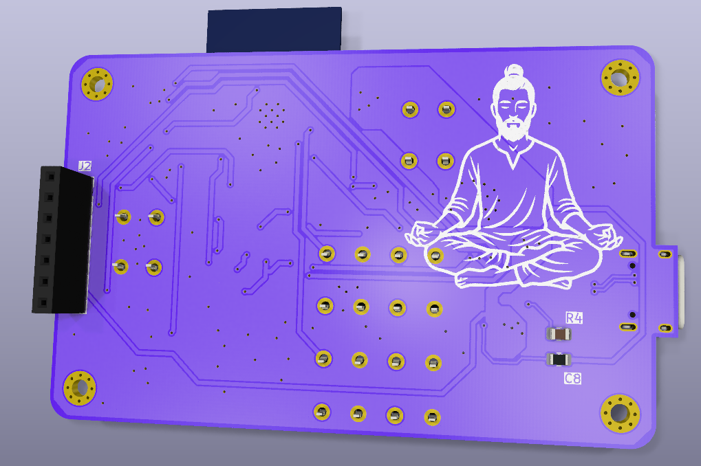
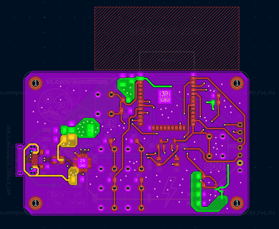
| Block | Component | Purpose |
|---|---|---|
| MCU | ESP32-WROOM-32 | Main processor with WiFi & Bluetooth |
| USB-UART | CP2102-GM | USB-to-serial bridge for flashing & debug |
| Auto-reset | 2× SS8050 (NPN) | Automatic bootloader entry during upload |
| Power | AMS1117-3.3 | 5 V → 3.3 V linear regulator |
| Sensor | BME280 | Temperature, humidity, pressure (I²C) |
| ESD | USBLC6-2SC6 | USB data line surge protection |
| Display | 7-pin SPI header | Modular TFT screen connection |
| Input | 4× tactile buttons | On-device menu navigation |
| Connector | USB-C (USB 2.0) | Power + data |
| Function | ESP32 Pin | Notes |
|---|---|---|
| UART TX | GPIO1 | To CP2102 |
| UART RX | GPIO3 | From CP2102 |
| I²C SDA | GPIO21 | BME280 |
| I²C SCL | GPIO22 | BME280 |
| Display SCK | GPIO18 | SPI clock (VSPI) |
| Display MOSI | GPIO23 | SPI data (VSPI) |
| Display CS | GPIO5 | Chip select |
| Display DC | GPIO16 | Data/command |
| Display RST | GPIO4 | Reset |
| Button UP | GPIO32 | Internal pull-up |
| Button DOWN | GPIO33 | Internal pull-up |
| Button OK | GPIO25 | Internal pull-up |
| Button BACK | GPIO26 | Internal pull-up |
💡 The firmware is up to you. The hardware gives you a full WiFi-enabled ESP32 with a sensor, a screen, and four buttons — what it displays and how it behaves is entirely programmable.
``` WeatherStation/ ├── WeatherStation.kicad_pro # KiCad project ├── WeatherStation.kicad_sch # Schematic ├── WeatherStation.kicad_pcb # PCB layout ├── WeatherStation.csv # Bill of Materials ├── libs/ # Local symbols & footprints │ ├── symbols/ │ └── footprints/ ├── Gerber/ # Manufacturing files └── docs/ └── images/ # Renders & screenshots ```
This project is released under the MIT License — free to use, study, modify, and distribute. See the LICENSE file for the full text.
[blocked]
Компактная метеостанция с WiFi на базе ESP32-WROOM-32.
Собственная двухслойная плата, спроектированная с нуля в KiCad.
VLASOV INDUSTRIES


Это полностью самостоятельная плата метеостанции на базе ESP32-WROOM-32. В отличие от обычного прототипа на макетке, здесь каждый компонент расположен на специально спроектированной плате — от моста USB-UART до стабилизации питания, интерфейса датчика и модульного разъёма для дисплея.
Устройство измеряет локальную обстановку встроенным датчиком BME280 (температура, влажность и атмосферное давление), а благодаря встроенному WiFi в ESP32 может получать актуальные данные о погоде из интернета и выводить их на подключённый экран. Четыре кнопки навигации позволяют переключать экраны и перемещаться по меню прямо на устройстве — компьютер после прошивки не нужен.
Поскольку в основе платы лежит полноценный ESP32 с WiFi, это намного больше чем просто термометр. Это открытая программируемая платформа: её можно расширить для показа прогнозов, нескольких городов, индексов качества воздуха, времени восхода и заката, оповещений — по сути всего что доступно из любого погодного API, и управлять всем этим четырьмя встроенными кнопками.
| Блок | Компонент | Назначение |
|---|---|---|
| Микроконтроллер | ESP32-WROOM-32 | Основной процессор с WiFi и Bluetooth |
| USB-UART | CP2102-GM | Мост USB-в-serial для прошивки и отладки |
| Автосброс | 2× SS8050 (NPN) | Автоматический вход в загрузчик при прошивке |
| Питание | AMS1117-3.3 | Линейный стабилизатор 5 В → 3.3 В |
| Датчик | BME280 | Температура, влажность, давление (I²C) |
| Защита ESD | USBLC6-2SC6 | Защита линий данных USB от разрядов |
| Дисплей | 7-пиновый SPI-разъём | Подключение модульного TFT-экрана |
| Ввод | 4× тактовые кнопки | Навигация по меню на устройстве |
| Разъём | USB-C (USB 2.0) | Питание + данные |
| Функция | Вывод ESP32 | Примечание |
|---|---|---|
| UART TX | GPIO1 | К CP2102 |
| UART RX | GPIO3 | От CP2102 |
| I²C SDA | GPIO21 | BME280 |
| I²C SCL | GPIO22 | BME280 |
| Дисплей SCK | GPIO18 | Тактирование SPI (VSPI) |
| Дисплей MOSI | GPIO23 | Данные SPI (VSPI) |
| Дисплей CS | GPIO5 | Выбор чипа |
| Дисплей DC | GPIO16 | Данные/команда |
| Дисплей RST | GPIO4 | Сброс |
| Кнопка ВВЕРХ | GPIO32 | Внутренняя подтяжка |
| Кнопка ВНИЗ | GPIO33 | Внутренняя подтяжка |
| Кнопка OK | GPIO25 | Внутренняя подтяжка |
| Кнопка НАЗАД | GPIO26 | Внутренняя подтяжка |
💡 Прошивка — за тобой. Железо даёт полноценный ESP32 с WiFi, датчиком, экраном и четырьмя кнопками. Что именно оно показывает и как себя ведёт — полностью программируется.
``` WeatherStation/ ├── WeatherStation.kicad_pro # Проект KiCad ├── WeatherStation.kicad_sch # Схема ├── WeatherStation.kicad_pcb # Разводка платы ├── WeatherStation.csv # Перечень компонентов (BOM) ├── libs/ # Локальные символы и посадочные места │ ├── symbols/ │ └── footprints/ ├── Gerber/ # Производственные файлы └── docs/ └── images/ # Рендеры и скриншоты ```
Проект распространяется под лицензией MIT — можно свободно использовать, изучать, изменять и распространять. Полный текст — в файле LICENSE.
Made with ⚡ by VLASOV INDUSTRIES
| Qty | Value | Footprint | References |
|---|---|---|---|
| 9 | 100nF | Capacitor_SMD:C_0805_2012Metric | C2, C3, C4, C5, C7, C8, C9, C12, C14 |
| 6 | SW_PUSH_6mm | Button_Switch_THT:SW_PUSH_6mm | SW1, SW2, SW3, SW4, SW5, SW6 |
| 4 | 10k | Resistor_SMD:R_0805_2012Metric | R1, R5, R6, R7 |
| 4 | LOGO | LOGO | G***, G***, G***, G*** |
| 3 | 4,7k | Resistor_SMD:R_0805_2012Metric | R4, R8, R9 |
| 2 | 10uF | Capacitor_SMD:C_1206_3216Metric | C6, C11 |
| 2 | 1μF | Capacitor_SMD:C_1206_3216Metric | C1, C10 |
| 2 | 5,1k | Resistor_SMD:R_0805_2012Metric | R2, R3 |
| 2 | SS8050 | Package_TO_SOT_SMD:SOT-23 | Q1, Q2 |
| 1 | 22uF | Capacitor_SMD:C_1206_3216Metric | C13 |
| 1 | AMS1117-3.3 | Package_TO_SOT_SMD:SOT-223-3_TabPin2 | U4 |
| 1 | BME280 | Package_LGA:Bosch_LGA-8_2.5x2.5mm_P0.65mm_ClockwisePinNumbering | U5 |
| 1 | CP2102-GM | CP2102-LOCAL:CP2102-GM | U3 |
| 1 | Conn_01x07 | Connector_PinSocket_2.54mm:PinSocket_1x07_P2.54mm_Vertical | J2 |
| 1 | ESP32-WROOM-32 | RF_Module:ESP32-WROOM-32 | U2 |
| 1 | USBLC6-2SC6 | Package_TO_SOT_SMD:SOT-23-6 | U1 |
| 1 | USB_C_Receptacle_USB2.0_16P | Connector_USB:USB_C_Receptacle_HCTL_HC-TYPE-C-16P-01A | J1 |
The 42 most common of 46 parts.
Blackcastus/ESP32_A7670
To make it easy for you to get started with GitLab, here's a list of recommended next steps.


VinayGopi-PK/ESP32-4-Channel-WiFi-Home-Automation
ESP32-based 4-channel Wi-Fi Home Automation Controller designed in KiCad. Includes schematic, PCB layout, Gerber files, BOM and 3D visualization.

PriyaUdhayakumar/ESP32-Environmental-Monitoring-Data-Logger
ESP32-based environmental monitoring data logger using BME280, DS3231 RTC, microSD card, ESP-IDF and FreeRTOS.


manhtienvu-vn/Defensive_Robot
Full neccessary document my team PKA-03 (Phenikaa University) used to build a defensive robot in the Vietnam Robocon competition 2025, including firmware, hardware and mechanical design.


It measures 77.5 × 48 mm and has 2 copper layers, 1.6 mm thick.
46 parts, built around the ESP32-WROOM-32, BME280, CP2102-GM and AMS1117-3.3. The full list of its parts is on this page, with links to each part's symbol and footprint where PCBKit's library has them.
From the Gleb-Vlasov/WeatherStation repository on GitHub, at the commit this page was made from: the board is WeatherStation.kicad_pcb and its schematic WeatherStation.kicad_sch. PCBKit opens the board in the browser, with nothing to install.
Its repository publishes it under the MIT licence: you may reuse it on that licence's terms (keep the author's notice, and for a copyleft licence share your changes alike).