
2 layers43 × 35 mm
LYFT CTRL
mgkoenig/lyft
LYFT is a sophisticated remote control for your IKEA BEKANT desk.
43 parts88GPL-3.0

 GerritMihu/SMT-Transistor-Blinki
Astabile Kippstufe mit SMT Bauteilen
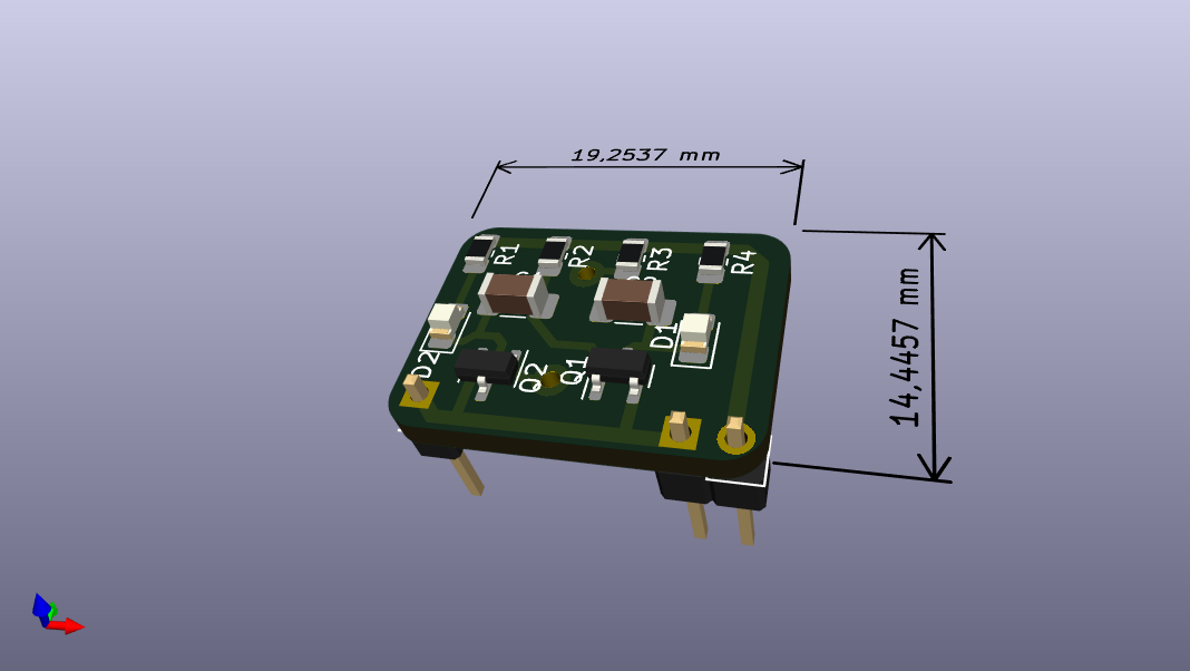
SMD Transistor Blinker is an open-source printed circuit board by GerritMihu, from the GerritMihu/SMT-Transistor-Blinki repository on GitHub. It is a 2-layer board of 19.3 × 14.4 mm with 12 parts on 8 nets, routed with 51 tracks and 2 vias.
It is built around the BC846. Its parts include 4 resistors, 2 capacitors, 2 diodes, 2 transistors and 2 connectors.
Ein Widerstand (R1-R4) ist ein elektronisches Bauteil, das den Stromfluss in einem Stromkreis begrenzt oder reguliert. Er wandelt einen Teil der elektrischen Energie in Wärme um und beeinflusst so, wie viel Strom durch einen bestimmten Teil eines Stromkreises fließen kann.
Ein Kondensator (C1 & C2) ist ein elektronisches Bauteil, das elektrische Energie speichert. Er besteht aus zwei leitfähigen Flächen, den sogenannten Platten, die durch ein Isoliermaterial (das Dielektrikum) voneinander getrennt sind. Die Hauptfunktion eines Kondensators ist es, Ladung zu speichern und bei Bedarf wieder abzugeben.
Eine LED (Light Emitting Diode D1 & D2) ist ein elektronisches Bauteil, das Licht erzeugt, wenn elektrischer Strom durch es hindurchfließt.
Ein Transistor (Q1 & Q2) ist ein elektronisches Bauteil, das als Schalter oder Verstärker fungiert. Er besteht aus Halbleitermaterialien und hat drei Anschlüsse: Emitter, Basis und Kollektor. Transistoren sind sehr wichtig für die Elektronik, da sie den Stromfluss steuern und Verstärkungsfunktionen ermöglichen.
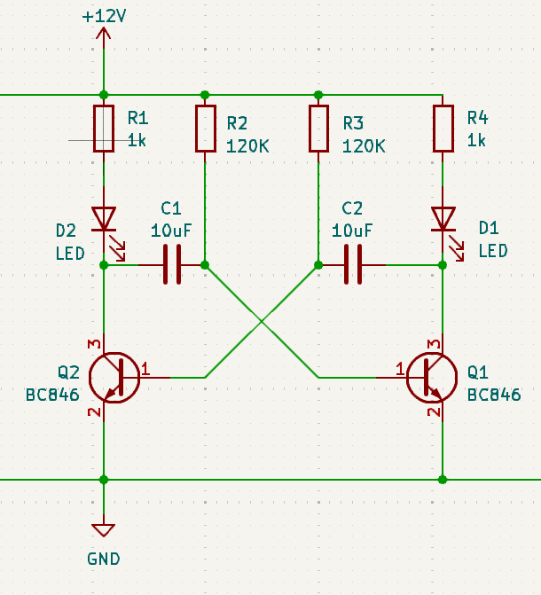
Die Schaltung basiert auf einem Astabilen Multivibrator, der die beiden Transistoren in einem wechselseitigen Betrieb schaltet. Der erste Transistor (Q1) schaltet die erste LED und der zweite Transistor (Q2) schaltet die zweite LED ein und aus. Dabei wechseln sich die LEDs ab, was das typische „Blinken“ erzeugt.
Ein astabiler Multivibrator ist eine elektronische Schaltung, die ständig zwischen zwei Zuständen hin- und herschaltet, ohne eine externe Steuerung.
Der J1 ist der Eingang, hier wird die Spannung angelegt. Entweder nimmt man zwei polige Stiftleisten oder einfach zwei Drähte.
Lötstation
Feine Lötspitze für präzises Arbeiten
Lötzinn
Multimeter, das man die Polung und den Wert der Bauteile zuordnen kann
Pinzette
Lötsaugpumpe, Lötsauglitze
Sie können dieses HTML Dokument als unterstützung nutzen um hier ihren Fortschritt zu dokumentieren: BOM
Lötzinn auf der Platine: Setze eine kleine Menge Lötzinn an einem der Lötpads an, um es vorzubereiten.
Platziere das SMD-Bauteil an der vorgesehenen Stelle auf der Platine mit einer Pinzette. Achte darauf, dass es korrekt ausgerichtet ist (markierte Seiten beachten).
Erhitze das Bauteil: Halte die Spitze des Lötkolbens für ca. 3-10 Sekunden auf das Bauteilbein und das Lötpad. Achte darauf, dass beide Teile warm werden, bevor du das Lötzinn zuführst.
Überprüfe die Lötstelle: Die Lötverbindung sollte glänzend und gleichmäßig sein. Vermeide kalte Lötstellen oder Lötbrücken.
A resistor (R1-R4) is an electronic component that limits or regulates the flow of current in a circuit. It converts some electrical energy into heat, influencing how much current can flow through a particular part of a circuit.
A capacitor (C1 & C2)is an electronic component that stores electrical energy. It consists of two conductive surfaces, called plates, which are separated from each other by an insulating material (the dielectric). The main function of a capacitor is to store charge and release it when needed.
An LED (Light Emitting Diode D1 & D2) is an electronic component that produces light when electric current flows through it.
A transistor (Q1 & Q2) is an electronic component that functions as a switch or amplifier. It is made of semiconductor materials and has three connections: emitter, base and collector. Transistors are very important in electronics because they control the flow of current and enable amplification functions.
The circuit is based on an astable multivibrator that switches the two transistors in alternating operation. The first transistor (Q1) switches the first LED and the second transistor (Q2) switches the second LED on and off. The LEDs alternate, which creates the typical “flashing”.
An astable multivibrator is an electronic circuit that constantly switches between two states without any external control.
J1 is the input, this is where the voltage is applied. Either you use two-pin pin strips or simply two wires.
Solderingstation
Fine soldering tip for precise work
Solder
Multimeter, which can be used to determine the polarity and value of the components
Tweezers
Solder suction pump, solder suction wire
You can use this dokument to help you with the placement process: BOM
Apply a small amount of solder to one of the soldering pads to prepare it.
Place the SMD component in the intended location on the circuit board using tweezers. Make sure it is aligned correctly (note marked sides).
Heat the component: Hold the tip of the soldering iron on the component leg and the soldering pad for approx. 3-10 seconds. Make sure both parts get warm before adding the solder.
Check the solder joint: The solder joint should be shiny and even. Avoid cold solder joints or solder bridges.
| Qty | Value | Footprint | References |
|---|---|---|---|
| 2 | 10uF | Capacitor_SMD:C_1206_3216Metric_Pad1.33x1.80mm_HandSolder | C1, C2 |
| 2 | 120K | Resistor_SMD:R_0805_2012Metric_Pad1.20x1.40mm_HandSolder | R2, R3 |
| 2 | 1k | Resistor_SMD:R_0805_2012Metric_Pad1.20x1.40mm_HandSolder | R1, R4 |
| 2 | BC846 | Package_TO_SOT_SMD:SOT-23 | Q1, Q2 |
| 2 | LED | LED_SMD:LED_0805_2012Metric_Pad1.15x1.40mm_HandSolder | D1, D2 |
| 1 | Conn_01x02_Pin | Connector_PinHeader_2.54mm:PinHeader_1x02_P2.54mm_Vertical | J1 |
| 1 | PINHD_1x1_Male | Connector_PinHeader_2.54mm:PinHeader_1x01_P2.54mm_Vertical | J4 |
mgkoenig/lyft
LYFT is a sophisticated remote control for your IKEA BEKANT desk.

Open-Lab-Starter-Kit/OLSK-Small-CNC
Open Source CNC Milling machine - Small version - Open Lab Starter Kit

schlae/HardDriveInfo
Repair info and schematics for mostly older MFM hard drives


SP6GK/Forte-600-HF-RF-Amplifier
Project of 600 W LDMOS amlifier based on 2xMRF300.

theexperimentgroup/Atlas-FPGA
La placa ATLAS se diseña con el objetivo de crear un multicore basado en SBC (SINGLE BOARD COMPUTER).

teiram/calypso-cyc1000-board
DIY FPGA board based on Trenz Cyc1000 and Raspberry RP2040 MCU
It measures 19.3 × 14.4 mm and has 2 copper layers, 1.6 mm thick.
12 parts, built around the BC846. The full list of its parts is on this page, with links to each part's symbol and footprint where PCBKit's library has them.
From the GerritMihu/SMT-Transistor-Blinki repository on GitHub, at the commit this page was made from: the board is SMD-Transistor-Blinker.kicad_pcb and its schematic SMD-Transistor-Blinker.kicad_sch. PCBKit opens the board in the browser, with nothing to install.
Its repository states no licence, so its author keeps all rights: ask GerritMihu before reusing the design.