2 layers18.5 × 11.1 mm
Switch
byrantech/laptop
anyon_e, a highly integrated, high end, open source laptop. Attempt the impossible.
6 parts4.3kMIT

 Gavinduachintha/Lora-Receiver1
Mini LoRa Tracker powered by a Raspberry Pi Pico 2 MCU.
LoRa Tracker is an open-source printed circuit board by Gavinduachintha, from the Gavinduachintha/Lora-Receiver repository on GitHub, published under the Apache-2.0 licence. It is a 2-layer board of 69.5 × 54.5 mm with 6 parts on 40 nets, routed with 95 tracks and 8 vias.
Its parts include 4 connectors and 1 switch. It belongs with the radio and wireless boards and the RP2040 boards of this library.
A custom Raspberry Pi Pico 2-based LoRa receiver board designed and built as the base station receiver for the WildLife AI project.
The board receives real-time LoRa packets transmitted by the remote wildlife monitoring unit and provides the hardware interface required for the base station display and power system.
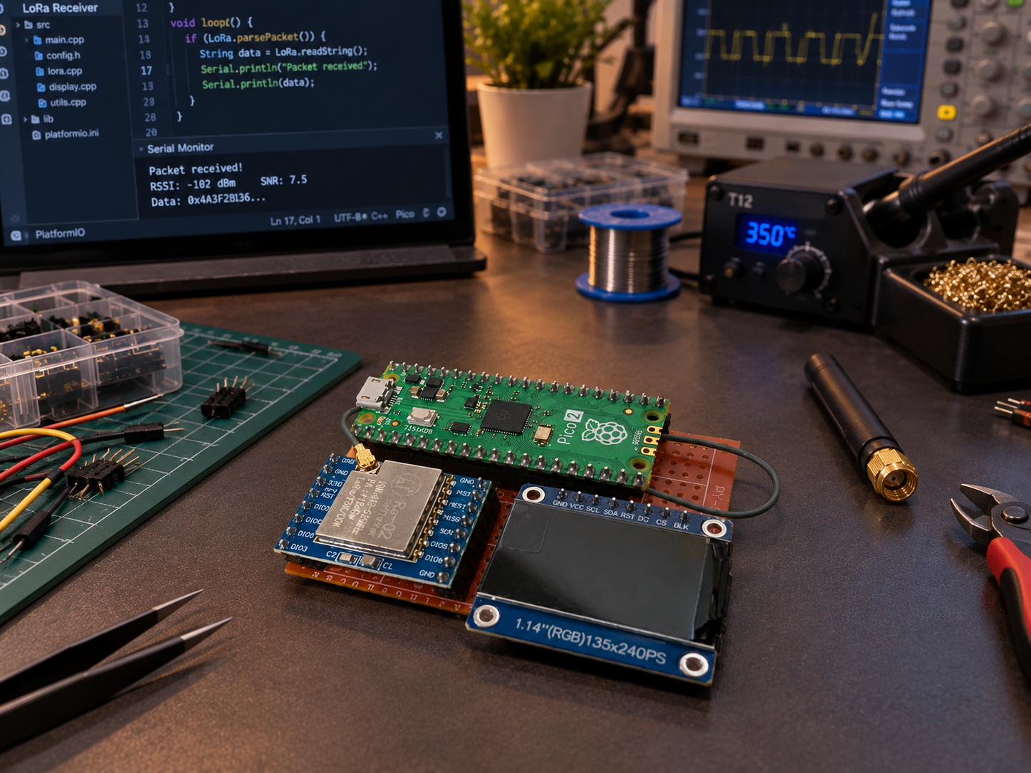
The LoRa Tracker is a custom PCB designed to serve as the receiver unit of the WildLife AI system.
It integrates a Raspberry Pi Pico 2 with dedicated interfaces for the LoRa transceiver, display, and battery power. The board replaces the earlier breadboard-based receiver prototype with a compact and more reliable PCB-based design.
The PCB provides dedicated headers for connecting the LoRa transceiver module.
Supported interface signals include:
A dedicated 8-pin header is provided for connecting the receiver display.
The interface includes signals such as:
The board includes:
The board was designed using KiCad with the Raspberry Pi Pico 2 positioned as the main controller module.
The PCB provides dedicated connection points for the LoRa module, display, and battery, allowing the receiver to be assembled without the wiring complexity of the original prototype.
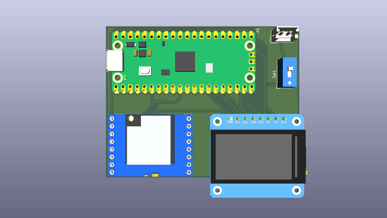
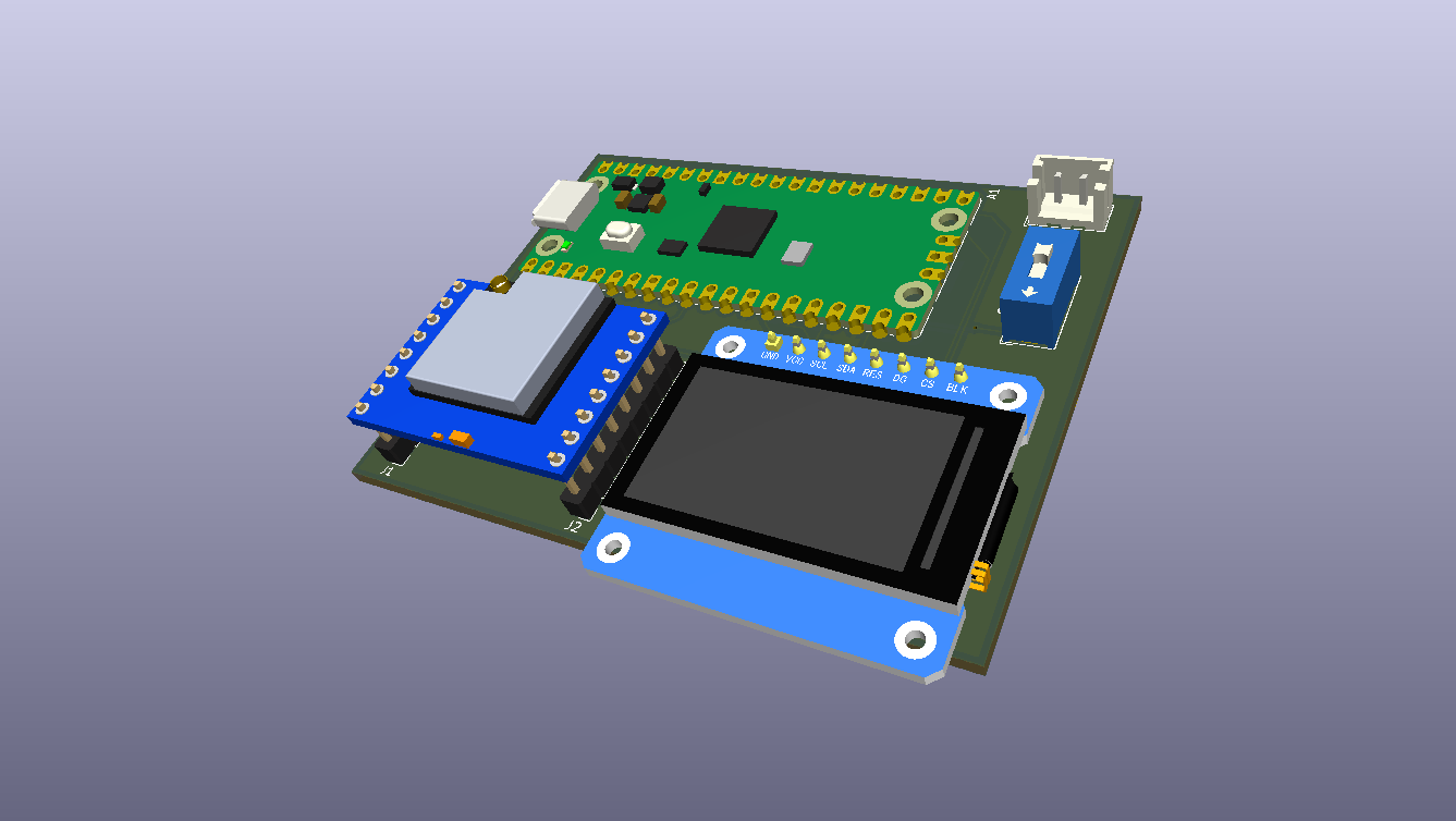
.
├── LoRa Tracker.kicad_pro   # KiCad project
├── LoRa Tracker.kicad_sch   # Schematic
├── LoRa Tracker.kicad_pcb   # PCB layout
└── Images/
    ├── Front Side.png
└── LoRa Tracker.pngThe project was designed using KiCad.
Open:
LoRa Tracker.kicad_profrom KiCad to access the schematic and PCB layout.
This receiver is part of the WildLife AI system.
The overall system consists of a remote monitoring device and this receiver/base station.
Remote Wildlife Monitor
        │
        │  LoRa
        ▼
┌─────────────────────┐
│   LoRa Tracker      │
│   Base Station      │
│                     │
│  Raspberry Pi Pico 2│
│  LoRa Interface     │
│  Display Interface  │
└─────────────────────┘
The remote unit collects information in the field and transmits it wirelessly through LoRa. The LoRa Tracker receives those packets and acts as the hardware foundation of the base station.
Learn more about the complete system:
Before manufacturing or modifying the board, the following checks should be performed:
The PCB has been designed and built as the receiver/base station hardware for the WildLife AI project.
The repository contains the KiCad source files required to inspect and continue development of the board.
Possible future revisions may include:
This project is licensed under the Apache License 2.0.
You are free to use, modify, and distribute this project in accordance with the terms of the license.
See the LICENSE file for the full license text.
| Qty | Value | Footprint | References |
|---|---|---|---|
| 1 | Battery Connector | Connector_JST:JST_EH_B2B-EH-A_1x02_P2.50mm_Vertical | J4 |
| 1 | Display Connector | Connector_PinHeader_2.54mm:PinHeader_1x08_P2.54mm_Vertical | J3 |
| 1 | LORA Left Side | Connector_PinHeader_2.54mm:PinHeader_1x08_P2.54mm_Vertical | J1 |
| 1 | LORA Right Side | Connector_PinHeader_2.54mm:PinHeader_1x08_P2.54mm_Vertical | J2 |
| 1 | Power Switch | Button_Switch_THT:SW_DIP_SPSTx01_Slide_9.78x4.72mm_W7.62mm_P2.54mm | SW1 |
| 1 | RaspberryPi_Pico | Module:RaspberryPi_Pico_Common_Unspecified | A1 |
byrantech/laptop
anyon_e, a highly integrated, high end, open source laptop. Attempt the impossible.


Jcparkyn/dpoint
Open-source digital stylus using camera tracking and inertial measurements

VoronDesign/Voron-Hardware
Cool Hardware designed by the Voron Design group

hoglet67/RGBtoHDMI
Bare-metal Raspberry Pi project that provides pixel-perfect sampling of Retro Computer RGB/YUV video and conversion to HDMI

hackclub/OnBoard
💡 Join 1,000 teenagers and make your first PCB with a $100 grant!

Luos-io/luos_engine
Open-source and real-time orchestrator for cyber-physical-systems, to easily design, test and deploy embedded applications and digital twins.

It measures 69.5 × 54.5 mm and has 2 copper layers, 1.6 mm thick.
6 parts. The full list of its parts is on this page, with links to each part's symbol and footprint where PCBKit's library has them.
From the Gavinduachintha/Lora-Receiver repository on GitHub, at the commit this page was made from: the board is LoRa Tracker.kicad_pcb and its schematic LoRa Tracker.kicad_sch. PCBKit opens the board in the browser, with nothing to install.
Its repository publishes it under the Apache-2.0 licence: you may reuse it on that licence's terms (keep the author's notice, and for a copyleft licence share your changes alike).