2 layers71.7 × 27.7 mm
GR KS0835F SLIC Breakout
GadgetReboot/KS0835F_Phone_SLIC
KS0835F phone line SLIC module breakout pcb
25 parts37

 GadgetReboot/Phone_SLIM62
POTS Telephone Subscriber Line Interface Module
GR Subscriber Line Interface Module is an open-source printed circuit board by GadgetReboot, from the GadgetReboot/Phone_SLIM repository on GitHub, published under the CC-BY-SA-4.0 licence. It is a 2-layer board of 99.4 × 99.6 mm with 112 parts on 99 nets, routed with 1,170 tracks and 173 vias.
It is built around the ICL7660N, LM358 and LD1117AV33, with the BZX55B2V4-TAP, HK19F-DC5V-SHG and P6KE82 among its other parts. Its parts include 28 resistors, 26 capacitors, 11 connectors, 9 diodes and 7 ICs. It belongs with the interfaces and adapters boards and the ESP32 boards of this library.


POTS Telephone Subscriber Line Interface Module
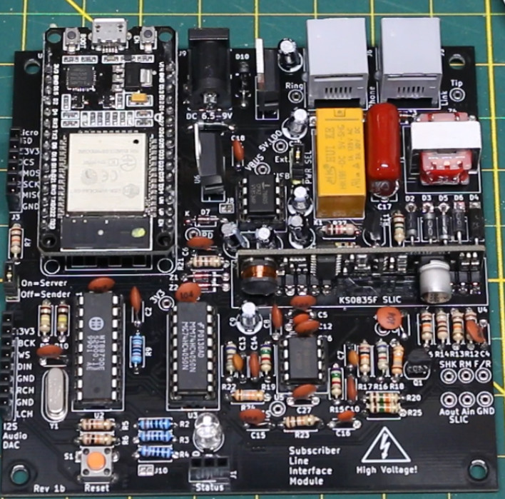
[!NOTE]
- This project is intended for hobby/personal use to explore how the plain old telephone service works.
- The PCB isn't designed to integrate with a live phone line. It is intended to create an offline system for local use.
It is recommended to add a TO-220 heat sink to the 3.3v regulator in case it gets too hot. I used Wakefield-Vette 274-3AB along with thermal paste and a nut/screw I had around.
One pcb is needed for each phone/modem/etc. One board has to have a jumper installed on J5 to act as a Server node and the other board(s) must have the jumper vacant to act as Sender nodes.
The Server board must connect to a WiFi router to function properly. The SSID and Password for the router must be defined by editing the "arduino_secrets.h" file before compiling the sketch.
The telephone numbers are 7 digits long and are configured by editing the "project_globals.cpp" file and changing the numbers assigned to remotePhoneNumber and localPhoneNumber.
The region can be configured by uncommenting the desired line in the "project_globals.cpp" file, setting myRegion equal to North America or UK.
Each board should be powered from an external 5 volt DC supply capable of 500mA since each board can draw several hundred mA.
USB power can be used for programming and some testing, but the board may not be as stable as when powered externally.
Set the power jumper J8 for USB or EXT as needed.
Power up the Server board first and wait for the blue LED to light up on the ESP module's built in LED to indicate it has joined the WiFi router.
Then power up the Sender board so it can try to auto-pair with the Server board over ESP-NOW. In the future, software may be improved so the Sender board will auto-pair whenever the Server board is ready.
Check out this similar project being worked on: https://github.com/ktownsend-personal/RetroPhone
Shield: 
This work is licensed under a Creative Commons Attribution-ShareAlike 4.0 International License.

| Qty | Value | Footprint | References |
|---|---|---|---|
| 15 | 100nF | Capacitor_THT:C_Disc_D4.3mm_W1.9mm_P5.00mm | C1, C2, C3, C4, C5, C6, C8, C10, C11, C14, C15, C18, C24, C25, C26 |
| 14 | TestPoint | TestPoint:TestPoint_Loop_D2.60mm_Drill1.4mm_Beaded | TP1, TP2, TP3, TP4, TP5, TP6, TP7, TP8, TP9, TP10, TP11, TP12, TP13, TP14 |
| 9 | 10K | Resistor_THT:R_Axial_DIN0207_L6.3mm_D2.5mm_P10.16mm_Horizontal | R2, R5, R6, R7, R12, R13, R17, R23, R26 |
| 6 | 10uF | Capacitor_THT:CP_Radial_D5.0mm_P2.50mm | C9, C19, C20, C21, C22, C23 |
| 5 | 1N4004 | Diode_THT:D_DO-41_SOD81_P10.16mm_Horizontal | D2, D3, D5, D6, D8 |
| 4 | BZX55B2V4-TAP | digikey-footprints:DO-35 | Z1, Z2, Z3, Z4 |
| 4 | MountingHole | MountingHole:MountingHole_3.2mm_M3 | MH1, MH2, MH3, MH4 |
| 3 | 100K | Resistor_THT:R_Axial_DIN0207_L6.3mm_D2.5mm_P10.16mm_Horizontal | R8, R10, R28 |
| 3 | 300r | Resistor_THT:R_Axial_DIN0207_L6.3mm_D2.5mm_P10.16mm_Horizontal | R1, R3, R4 |
| 3 | 7.5K | Resistor_THT:R_Axial_DIN0207_L6.3mm_D2.5mm_P10.16mm_Horizontal | R15, R19, R25 |
| 2 | 100r | Resistor_THT:R_Axial_DIN0207_L6.3mm_D2.5mm_P10.16mm_Horizontal | R14, R21 |
| 2 | 18K | Resistor_THT:R_Axial_DIN0207_L6.3mm_D2.5mm_P10.16mm_Horizontal | R18, R24 |
| 2 | 1nF | Capacitor_THT:C_Disc_D4.3mm_W1.9mm_P5.00mm | C12, C16 |
| 2 | 6.8K | Resistor_THT:R_Axial_DIN0207_L6.3mm_D2.5mm_P10.16mm_Horizontal | R16, R22 |
| 2 | 6.8nF | Capacitor_THT:C_Disc_D4.3mm_W1.9mm_P5.00mm | C7, C13 |
| 2 | Conn_01x03 | Connector_PinHeader_2.54mm:PinHeader_1x03_P2.54mm_Vertical | J1, J8 |
| 2 | Jumper | Jumper:SolderJumper-2_P1.3mm_Bridged_Pad1.0x1.5mm | J3, J9 |
| 2 | RJ | footprints:RJ_6p6c | J6, J7 |
| 1 | 1 MEG | Resistor_THT:R_Axial_DIN0207_L6.3mm_D2.5mm_P10.16mm_Horizontal | R11 |
| 1 | 15K | Resistor_THT:R_Axial_DIN0207_L6.3mm_D2.5mm_P10.16mm_Horizontal | R20 |
| 1 | 1825910-6 | digikey-footprints:Switch_Tactile_THT_6x6mm | S1 |
| 1 | 1K | Resistor_THT:R_Axial_DIN0207_L6.3mm_D2.5mm_P10.16mm_Horizontal | R27 |
| 1 | 1N4148 | Diode_THT:D_DO-35_SOD27_P7.62mm_Horizontal | D7 |
| 1 | 1N5817 | digikey-footprints:DO-41 | D9 |
| 1 | 1uF 250V | Capacitor_THT:C_Rect_L16.5mm_W5.0mm_P15.00mm_MKT | C17 |
| 1 | 2N3904 | Package_TO_SOT_THT:TO-92_Inline_Wide | Q2 |
| 1 | 2N7000 | Package_TO_SOT_THT:TO-92_Inline | Q1 |
| 1 | 3.579545 MHz | Crystal:Crystal_HC49-4H_Vertical | Y1 |
| 1 | 300K | Resistor_THT:R_Axial_DIN0207_L6.3mm_D2.5mm_P10.16mm_Horizontal | R9 |
| 1 | 4050 | Package_DIP:DIP-16_W7.62mm_Socket_LongPads | U3 |
| 1 | 600:600 | footprints:Transformer_600_600 | T1 |
| 1 | Conn_01x02 | Connector_PinHeader_2.54mm:PinHeader_1x02_P2.54mm_Vertical | J5 |
| 1 | Conn_01x06 | Connector_PinHeader_2.54mm:PinHeader_1x06_P2.54mm_Vertical | J4 |
| 1 | Conn_01x08 | Connector_PinHeader_2.54mm:PinHeader_1x08_P2.54mm_Vertical | J2 |
| 1 | ESP32_DevKit_V1_DOIT | footprints:esp32_devkit_v1_doit | U1 |
| 1 | HK19F-DC5V-SHG | Relay_THT:Relay_DPDT_Omron_G5V-2 | K1 |
| 1 | ICL7660 | Package_DIP:DIP-8_W7.62mm_Socket | U7 |
| 1 | KS0835F | footprints:KS0835F | U4 |
| 1 | LD1117AV33 | Package_TO_SOT_THT:TO-220-3_Vertical | U6 |
| 1 | LED_RAGB | LED_THT:LED_D5.0mm-4_RGB | D1 |
| 1 | LM358 | Package_DIP:DIP-8_W7.62mm_Socket | U5 |
| 1 | LOGO | _Custom_Footprints:pcb way logo | G*** |
| 1 | MT8870DE | Package_DIP:DIP-18_W7.62mm_Socket | U2 |
| 1 | P6KE82 | Diode_THT:D_DO-15_P10.16mm_Horizontal | D4 |
| 1 | PJ-202A | digikey-footprints:Barrel_Jack_5.5mmODx2.1mmID_PJ-202A | J10 |
| 1 | Screw_Terminal_01x02 | TerminalBlock:TerminalBlock_bornier-2_P5.08mm | J11 |
The 110 most common of 112 parts.
GadgetReboot/KS0835F_Phone_SLIC
KS0835F phone line SLIC module breakout pcb

ryukoposting/SimpleSLIC
Serve a simple telephone line with a microcontroller


crgarcia12/electronics-homeassistant-lightscontroll
A smart lighting controller PCB that integrates seamlessly with ESPHome and Home Assistant while maintaining full compatibility with traditional mechanical switches.


richardhoman99/Single-Board-Computer
CPGR4253 Microcomputer Design is not as much a technical course at LeTourneau University as it is a design project.

wyolum/ESP8266_01_Breakout
KiCad fork of https://github.com/sfgit/ESP8266-01-BREAKOUT

bismarx-v1/Sumec-MiniSumo-HW
SUMEC is a MiniSumo robot designed by SPŠ na Proseku students. This repository contains hardware source for this project - PCB files and other electronics.
It measures 99.4 × 99.6 mm and has 2 copper layers, 1.6 mm thick.
112 parts, built around the ICL7660N, LM358, LD1117AV33 and BZX55B2V4-TAP. The full list of its parts is on this page, with links to each part's symbol and footprint where PCBKit's library has them.
From the GadgetReboot/Phone_SLIM repository on GitHub, at the commit this page was made from: the board is KiCad/GR_Subscriber_Line_Interface_Module.kicad_pcb. PCBKit opens the board in the browser, with nothing to install.
Its repository publishes it under the CC-BY-SA-4.0 licence: you may reuse it on that licence's terms (keep the author's notice, and for a copyleft licence share your changes alike).