4 layers95 × 113 mm

 FanieVenter/VNTR-651
A custom, over-engineered 65% keyboard featuring an RP2350 MCU, a hall effect key matrix, an analog slide potentiometer, an OLED display. Built for daily use thanks to HackClub.
VNTR-65 is an open-source printed circuit board by FanieVenter, from the FanieVenter/VNTR-65 repository on GitHub. It is a 2-layer board of 370 × 120 mm with 137 parts on 171 nets, routed with 5,663 tracks and 1,062 vias.
It is built around the W25Q128JVSIQ, CD74HC4067M and CH221K, with the A1002WR-S-3P and ABM8-272-T3 among its other parts. Its parts include 78 ICs, 24 capacitors, 17 resistors, 3 switches and 2 connectors. It belongs with the lEDs and displays and keyboards and input boards and the RP2350 boards of this library.


A custom, over-engineered 65% keyboard featuring an RP2350 MCU, a hall effect key matrix, an analog slide potentiometer, and an OLED display. Built for daily use thanks to Hack Club.
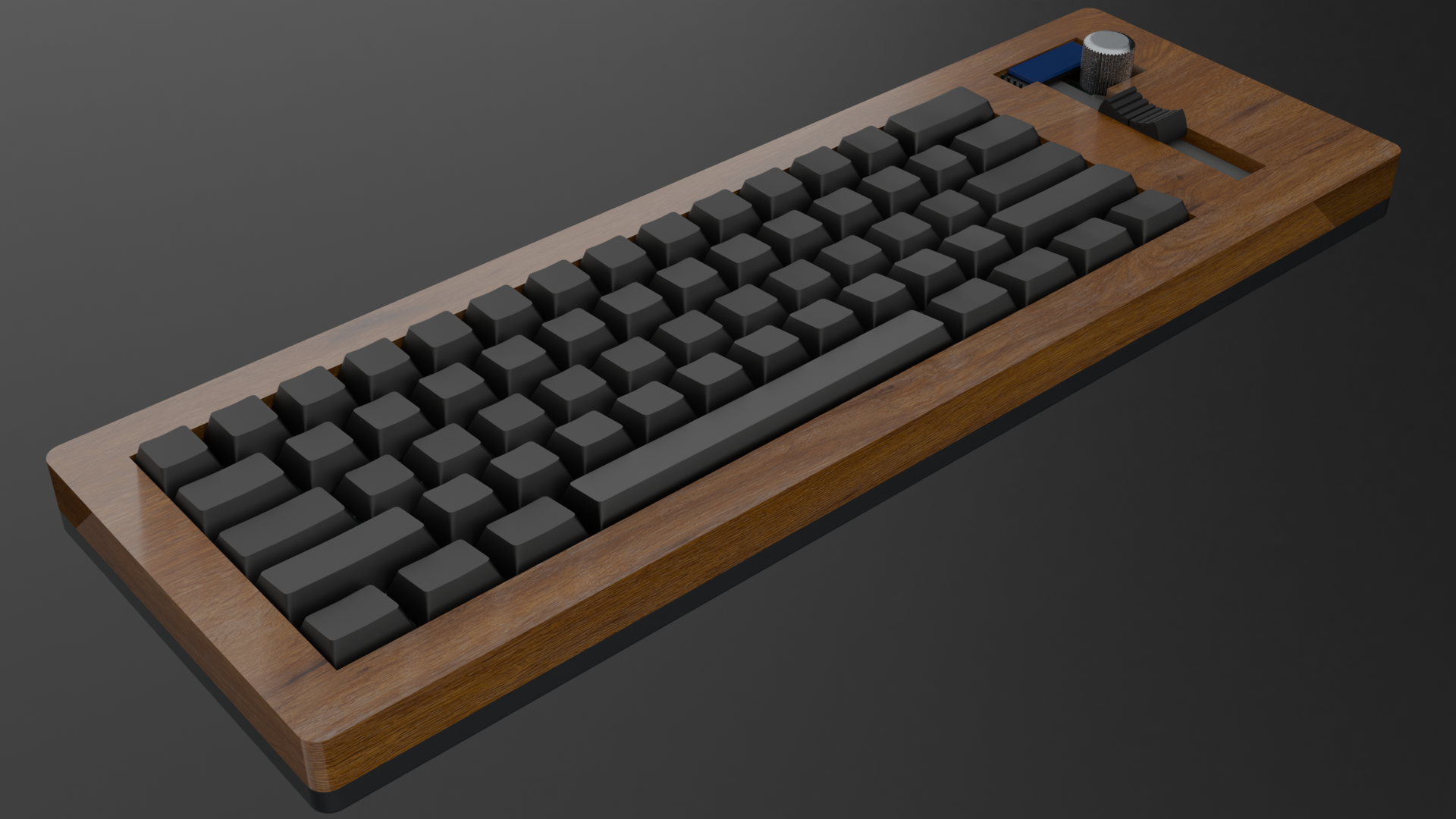
I wanted to build a nice keyboard that I could use every day at school while knowing it won't break, I also wanted to make a keyboard that used hall effect switches to allow for analog inputs in racing ganes like Assetto Corsa and giving me a more challenging and fun experience designing it.
To use this keyboard you will need to either download the production files for JLCPCB or create your own by exporting it them from Kicad. You will then need to place a order for the PCB using the productions files at your chosen pcb manufacturer. After you have received the PCB you will need to solder all the components onto the PCB and then flash the firmware onto the RP2350. While this is happening you can either 3d print the case or get it milled out of aluminum and wood. After you have the case and the PCB ready you can then assemble the keyboard and upload the firmware to the RP2350 and then you can use it.
I learn't how to design a keyboard from scratch using Kicad for the pcb. I also learn't how to use onshape after deciding to swap to it from Freecad a little bit because the projects says to have it in onshape but mostly as I had realised after 2 years of FreeCAD use that it wasn't powerful enough for me. I learn't how to take a raw wood texture file and make it look like a satin polyeuranted finished piece of wood in blender.
The cost of the pcba has gone down since I submitted the project for review. For updated pricing and screenshot check the BOM.
Onshape link for the Case.
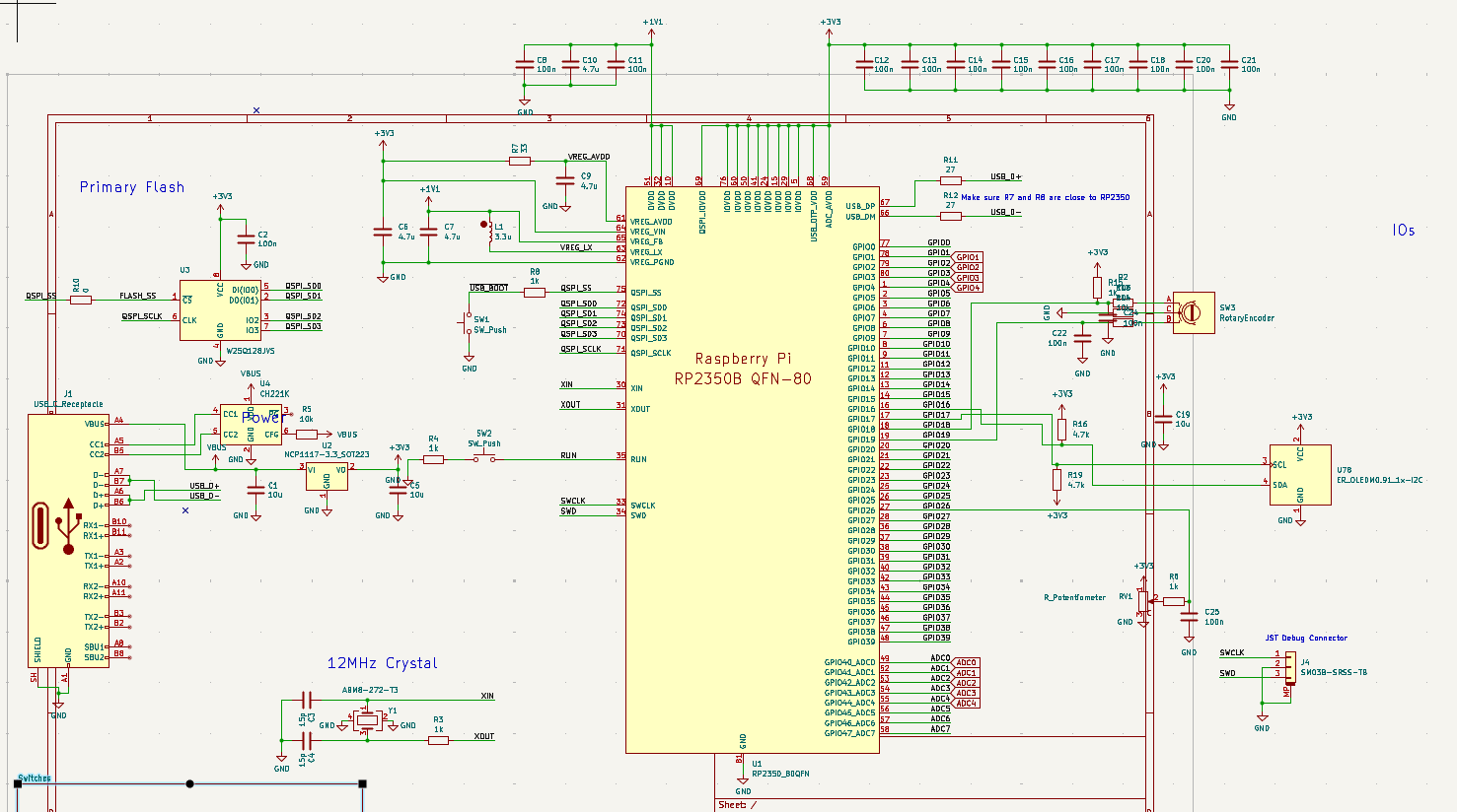
Main schematic.
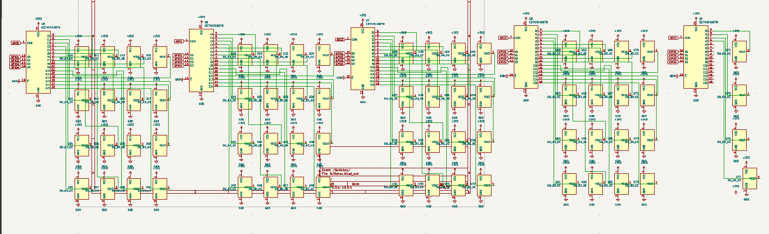
Hall effect switch matrix.
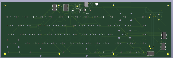
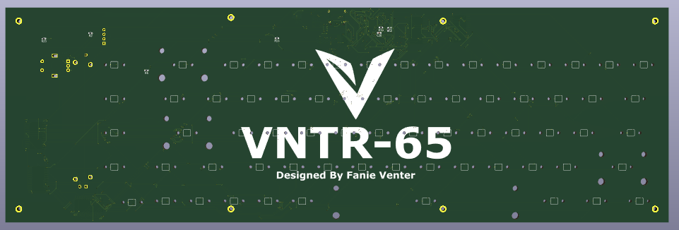
Front and back of the PCB — the back has the silkscreen applied.
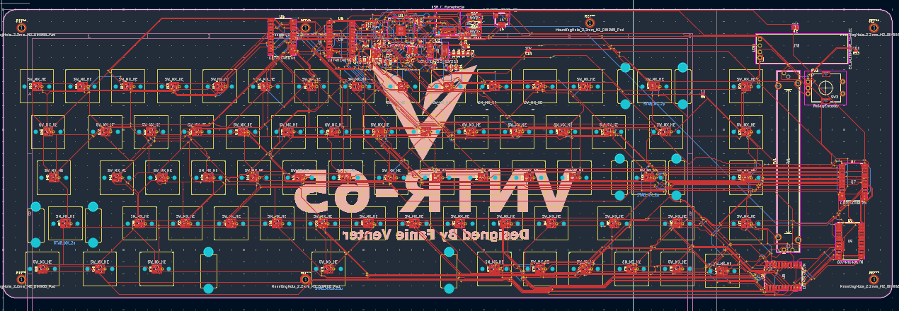
Full PCB wiring across all copper layers.
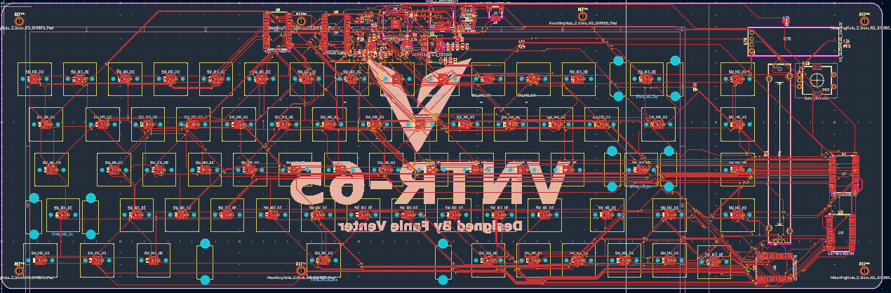
Full PCB wiring on the front copper layer.
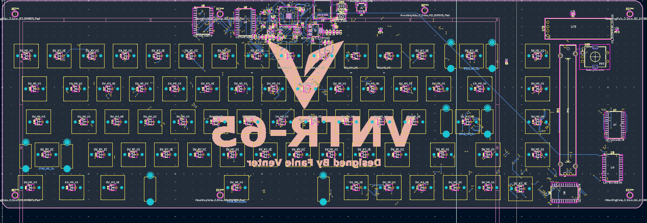
Full PCB wiring on the back copper layer.
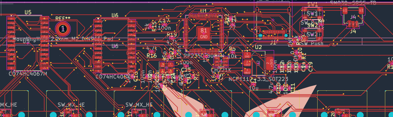
Main section wiring on the front copper layer.
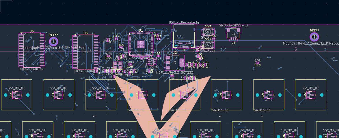
Main section wiring on the back copper layer.
| Qty | Value | Footprint | References |
|---|---|---|---|
| 68 | SW_MX_HE | PCM_marbastlib-he:SW_MX_HE_0deg_1u | U10, U11, U12, U13, U14, U15, U16, U17, U18, U19, U20, U21, U22, U23, U24, U25 +52 |
| 15 | 100n | Capacitor_SMD:C_0603_1608Metric | C2, C8, C11, C12, C13, C14, C15, C16, C17, C18, C20, C21, C22, C24, C25 |
| 5 | 1k | Resistor_SMD:R_0603_1608Metric | R3, R4, R6, R8, R15 |
| 5 | CD74HC4067M | Package_SO:SOIC-24W_7.5x15.4mm_P1.27mm | U5, U6, U7, U8, U9 |
| 4 | 10k | Resistor_SMD:R_0603_1608Metric | R2, R5, R13, R14 |
| 4 | 4.7u | Capacitor_SMD:C_0603_1608Metric | C6, C7, C9, C10 |
| 3 | 10u | Capacitor_SMD:C_0603_1608Metric | C1, C5, C19 |
| 2 | 15p | Capacitor_SMD:C_0603_1608Metric | C3, C4 |
| 2 | 27 | Resistor_SMD:R_0603_1608Metric | R11, R12 |
| 2 | 4.7k | Resistor_SMD:R_0603_1608Metric | R16, R19 |
| 2 | DNF | Resistor_SMD:R_0402_1005Metric | R1, R9 |
| 2 | SW_Push | Button_Switch_SMD:SW_Push_1P1T_NO_Vertical_Wuerth_434133025816 | SW1, SW2 |
| 1 | 0 | Resistor_SMD:R_0603_1608Metric | R10 |
| 1 | 33 | Resistor_SMD:R_0603_1608Metric | R7 |
| 1 | A1002WR-S-3P | Connector_JST:JST_SH_SM03B-SRSS-TB_1x03-1MP_P1.00mm_Horizontal | J4 |
| 1 | ABM8-272-T3 | Crystal:Crystal_SMD_3225-4Pin_3.2x2.5mm | Y1 |
| 1 | CH221K | Package_TO_SOT_SMD:SOT-23-6 | U4 |
| 1 | ER_OLEDM0.91_1x-I2C | Display:ER_OLEDM0.91_1x-I2C | U78 |
| 1 | NCP1117-3.3_SOT223 | Package_TO_SOT_SMD:SOT-223-3_TabPin2 | U2 |
| 1 | RP2350_80QFN | Package_DFN_QFN:QFN-80-1EP_10x10mm_P0.4mm_EP3.4x3.4mm | U1 |
| 1 | R_Potentiometer | PCM_Potentiometer_THT_AKL:Potentiometer_Bourns_PTA6043_Single_Slide | RV1 |
| 1 | RotaryEncoder | Rotary_Encoder:RotaryEncoder_Alps_EC11E-Switch_Vertical_H20mm | SW3 |
| 1 | USB_C_Receptacle | Connector_USB:USB_C_Receptacle_Amphenol_12401610E4-2A | J1 |
| 1 | W25Q128JVS | Package_SO:SOIC-8_3.9x4.9mm_P1.27mm | U3 |
The 126 most common of 137 parts.

jackw01/scanlight
A better light source for scanning color negative film

llextv/coreLight
CoreLight is an open-source DIY lighting controller built around an STM32H743.

Arkos-Engineering/HT-15_hardware
We can split this out into separate repos later, right now its very convenient to have everything here.

7west/PicoTop
A very basic computer & OS based on the RP2350 microcontroller

tihmstar/colobus_hardware
RP2040 based iPhone (lightning) UART cable, that actually works (hardware)

ikajdan/katia
A split keyboard with 6 by 3 column staggered keys and 3 thumb keys, based on the Crkbrd design

alvarop/swd2usbc
Have you ever wanted to debug your device over USB-C? Sometimes there's not enough room for a JTAG/SWD connector, or even Tag-Connect pads!
It measures 370 × 120 mm and has 2 copper layers, 1.6 mm thick.
137 parts, built around the W25Q128JVSIQ, CD74HC4067M, CH221K and A1002WR-S-3P. The full list of its parts is on this page, with links to each part's symbol and footprint where PCBKit's library has them.
From the FanieVenter/VNTR-65 repository on GitHub, at the commit this page was made from: the board is Hardware/PCB/VNTR-65.kicad_pcb and its schematic Hardware/PCB/Switches.kicad_sch. PCBKit opens the board in the browser, with nothing to install.
Its repository states no licence, so its author keeps all rights: ask FanieVenter before reusing the design.