Skip to the content
2 layers22 × 22 mmATTiny412-Breakout, the printed circuit board in 3D

Simple breakout for the ATTiny412 using USB for uploading and serial comms

Size
22 × 22 mm
Copper layers
2
Thickness
1.6 mm
Parts
26
Nets
32
Pads
102
Tracks, vias
285, 27
Pours
2
Routed
Yes
KiCad
KiCad 7 (file 20221018)
Created
10 Jul 2024
Updated
11 Jul 2024

Overview

ATTiny412-Breakout is an open-source printed circuit board by EzerLonginus, from the EzerLonginus/ATTiny412-Breakout repository on GitHub, published under the GPL-3.0 licence. It is a 2-layer board of 22 × 22 mm with 26 parts on 32 nets, routed with 285 tracks and 27 vias.

It is built around the ATTINY412-SSN, CH340E and USBLC6-2SC6. Its parts include 9 resistors, 4 ICs, 4 diodes, 4 connectors and 3 capacitors. It belongs with the interfaces and adapters boards and the AVR (ATmega, ATtiny) boards of this library.

Main components

3

README

README.md

ATTiny412-Breakout

Simple breakout for the ATTiny412 using USB for uploading and serial comms

This board is a simple breakout for the ATTiny412. This allows for programming and UART serial communications through a USB interface. Included in breakout is a power led indication, and a few feedback LEDs for UART and UPDI programming. UPDI and UART need to be selected via switch on the front of the breakout.

Purpose

I wanted a way to quickly and easily test some software with the attiny412 (or similar avr chip), and not have to have a programmer and separate power source connected to chip. This usually involved using a USB connector for power (sometimes doubling as a serial comms port) and some UPDI programmer to upload code. This board will hopefully just allow me to use the USB for all functionality and to make development a little be cleaner and easier.

Scematic
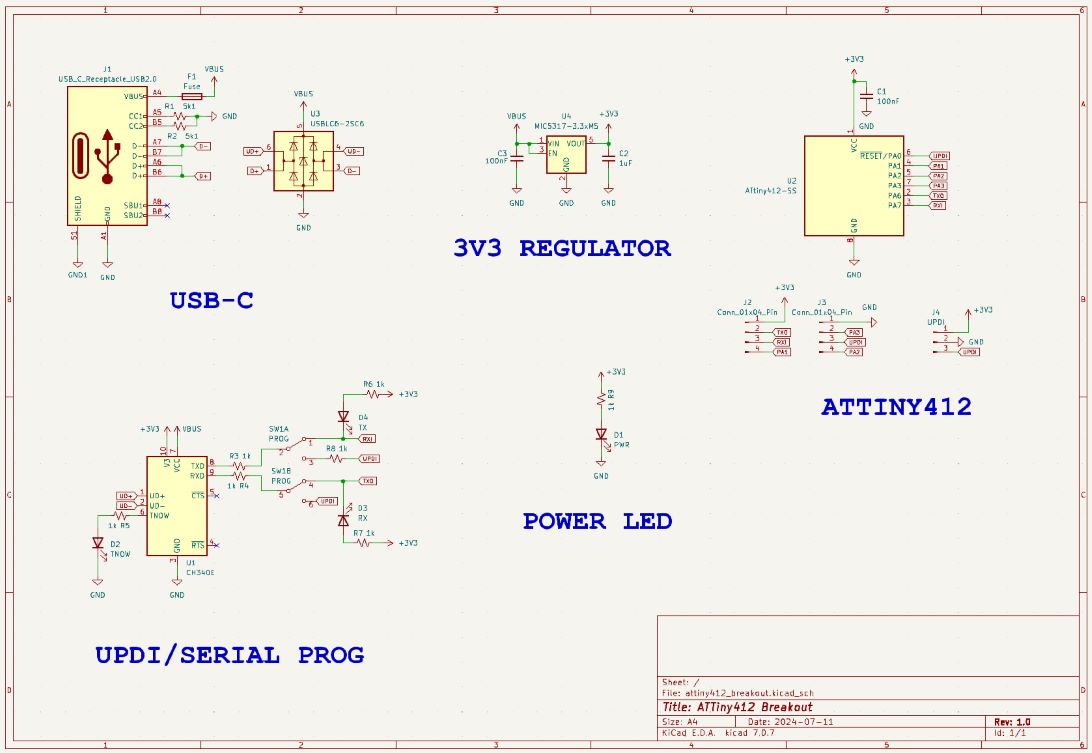
ATTiny412 Schematic

Layout

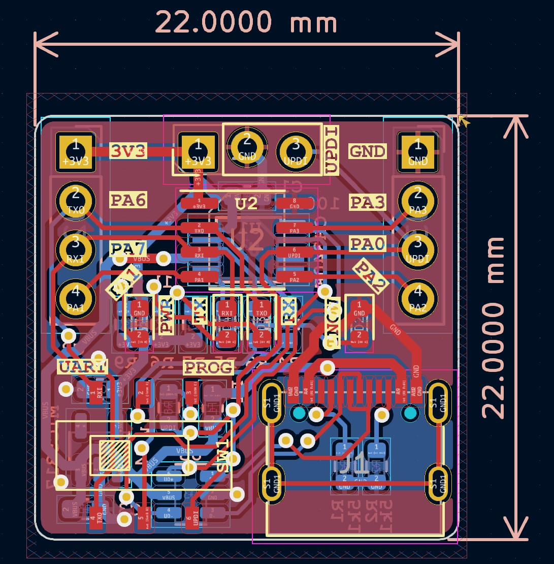
ATTiny412 Layout

3D Render

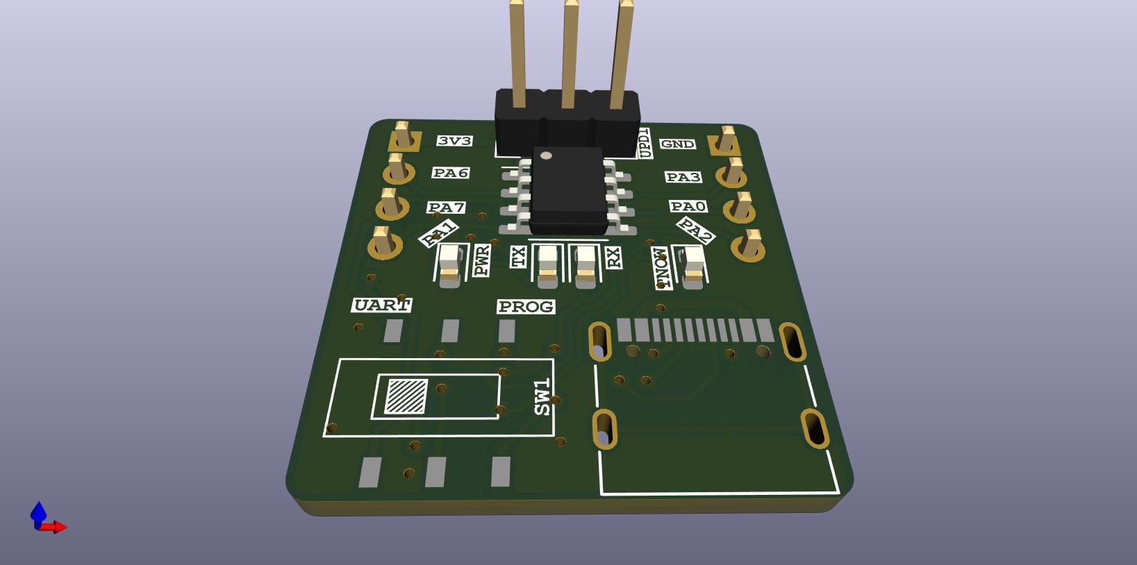
ATTiny412 Render

Current State of Affairs

Version 1

  • Populate and test board
  • Fix the inevitable issue that I missed during production

Parts

26
QtyValueFootprintReferences
71kResistor_SMD:R_0603_1608MetricR3, R4, R5, R6, R7, R8, R9
2100nFCapacitor_SMD:C_0603_1608MetricC1, C3
25k1Resistor_SMD:R_0603_1608MetricR1, R2
2Conn_01x04_PinConnector_PinHeader_2.54mm:PinHeader_1x04_P2.54mm_VerticalJ2, J3
1 TX LED_SMD:LED_0603_1608MetricD4
11uFCapacitor_SMD:C_0603_1608MetricC2
1ATtiny412-SSPackage_SO:SOIC-8_3.9x4.9mm_P1.27mmU2
1CH340EPackage_SO:MSOP-10_3x3mm_P0.5mmU1
1FuseFuse:Fuse_0603_1608MetricF1
1MIC5317Package_TO_SOT_SMD:SOT-23-5U4
1PROGELonginus:SMD DPDT Toggle SS-3235S-L1SW1
1PWRLED_SMD:LED_0603_1608MetricD1
1RXLED_SMD:LED_0603_1608MetricD3
1TNOWLED_SMD:LED_0603_1608MetricD2
1UPDIELonginus:1x3_2.54mm_pin_staggeredJ4
1USBLC6-2SC6Package_TO_SOT_SMD:SOT-23-6U3
1USB_C_Receptacle_USB2.0Connector_USB:USB_C_Receptacle_G-Switch_GT-USB-7010ASVJ1

Similar boards

  • 2 layers55.9 × 27.9 mmMSPM0uCBoard, the printed circuit board in 3D

    MSPM0uCBoard

    Choaib-ELMADI/pcb-projects

    This repository includes a collection of electronic PCB designs and custom KiCad libraries. It features various hardware projects, reusable components, and detailed documentation for learning and development.

    37 parts9
  • 4 layers55.8 × 20 mmWmbus, the printed circuit board in 3D

    Wmbus

    nobodyguy/wmbus_hardware

    WM-bus to USB

    27 parts7MIT
  • 2 layers59.5 × 27.2 mmMbus, the printed circuit board in 3D

    Mbus

    nobodyguy/mbus_hardware

    M-bus to USB

    39 parts2MIT
  • 2 layers58 × 37.1 mmPhils Lab #165, the printed circuit board in 3D

    Phils Lab #165

    ctrl-z3d/pcb-designs

    A personal archive of PCB projects I've designed and built along the way. Schematics, board layouts, manufacturing files, and notes.

    37 parts1
  • 2 layers54.1 × 31.8 mmIVME OLCER, the printed circuit board in 3D

    IVME OLCER

    hykoser/LIS2DH-Accelerometer-Board

    A custom accelerometer development board designed with KiCad and MSPM0 microcontroller.

    37 parts1
  • 2 layers53 × 28 mmMspmo baord, the printed circuit board in 3D

    Mspmo baord

    prashantbhandary/mspmo-baord

    A compact USB-C development board for TI's MSPM0G3507 (Arm Cortex-M0+, 80 MHz, 128 KB flash, 32 KB SRAM), with an on-board USB-to-UART bridge, a 3-axis accelerometer and a Tag-Connect SWD footprint.

    37 parts1
  • 2 layers52 × 30 mmTI MSPM0, the printed circuit board in 3D

    TI MSPM0

    shukushwaha/TI-MSPM0-KiCad-Development-Board

    Custom TI MSPM0 microcontroller development board designed using KiCad.

    37 parts1

Questions

How big is the ATTiny412-Breakout PCB?

It measures 22 × 22 mm and has 2 copper layers, 1.6 mm thick.

What parts does the ATTiny412-Breakout use?

26 parts, built around the ATTINY412-SSN, CH340E and USBLC6-2SC6. The full list of its parts is on this page, with links to each part's symbol and footprint where PCBKit's library has them.

Where can I download the ATTiny412-Breakout KiCad files?

From the EzerLonginus/ATTiny412-Breakout repository on GitHub, at the commit this page was made from: the board is hardware/attiny412_breakout/attiny412_breakout.kicad_pcb and its schematic hardware/attiny412_breakout/attiny412_breakout.kicad_sch. PCBKit opens the board in the browser, with nothing to install.

Can I use the ATTiny412-Breakout design in my own project?

Its repository publishes it under the GPL-3.0 licence: you may reuse it on that licence's terms (keep the author's notice, and for a copyleft licence share your changes alike).