
2 layers40.6 × 108 mm
Useq
Emute-Lab-Instruments/uSEQ
Hardware & firmware of the uSEQ Live Coding CV & Gate Sequencer
60 parts44
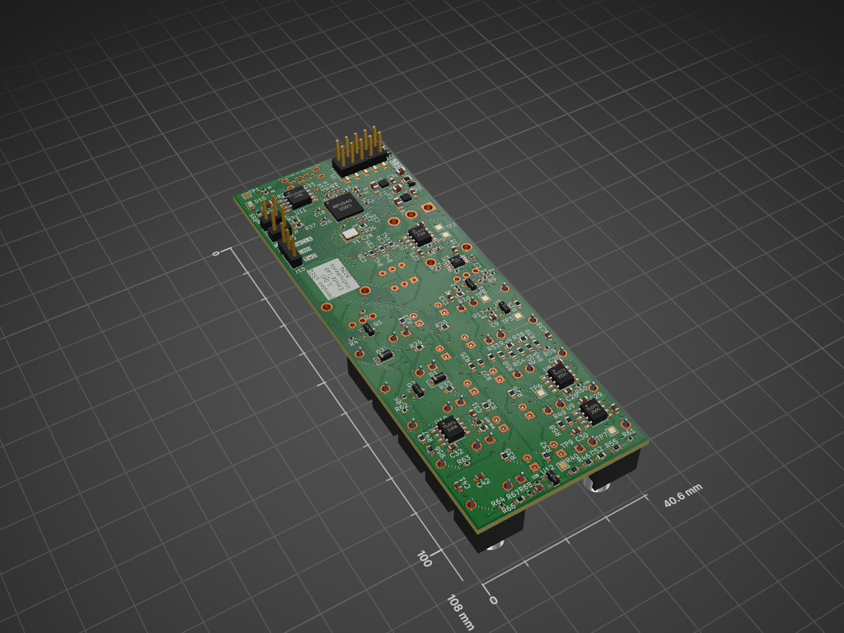
Hardware & firmware of the uSEQ Live Coding CV & Gate Sequencer
Useq1 is an open-source printed circuit board by Emute-Lab-Instruments, from the Emute-Lab-Instruments/uSEQ repository on GitHub. It is a 2-layer board of 40.6 × 108 mm with 172 parts on 128 nets, routed with 1,479 tracks and 208 vias.
It is built around the RP2040, TL072 and W25Q128JVSIQ, with the TLV76733DRVR, 1N4148W and B3U-1000P among its other parts. Its parts include 68 resistors, 42 capacitors, 15 diodes, 14 connectors and 12 ICs. It belongs with the RP2040 boards of this library.


uSEQ is a livecodeable eurorack module.
There's a paper on it here:
Kyriakoudis, Dimitris, & Kiefer, Chris. (2023, April 19). uSEQ: A LISPy Modular Sequencer for Eurorack with a Livecodable Microcontroller. 7th International Conference on Live Coding (ICLC2023), Utrecht, The Netherlands. https://doi.org/10.5281/zenodo.7843874
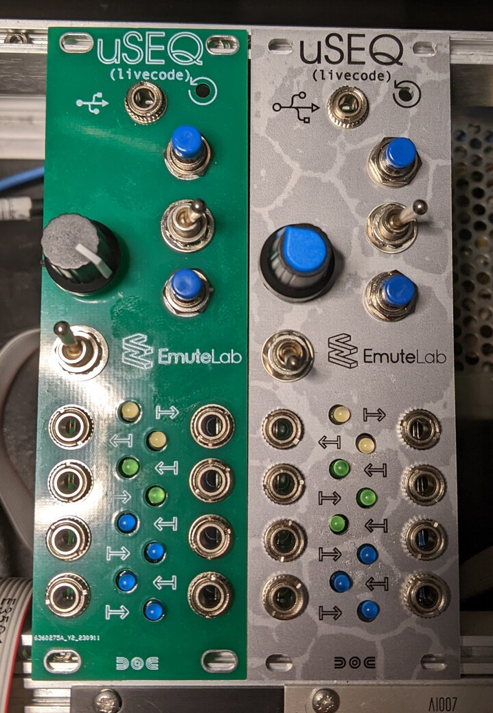
uSEQ modules, two panel designs (PCB, Aluminium)
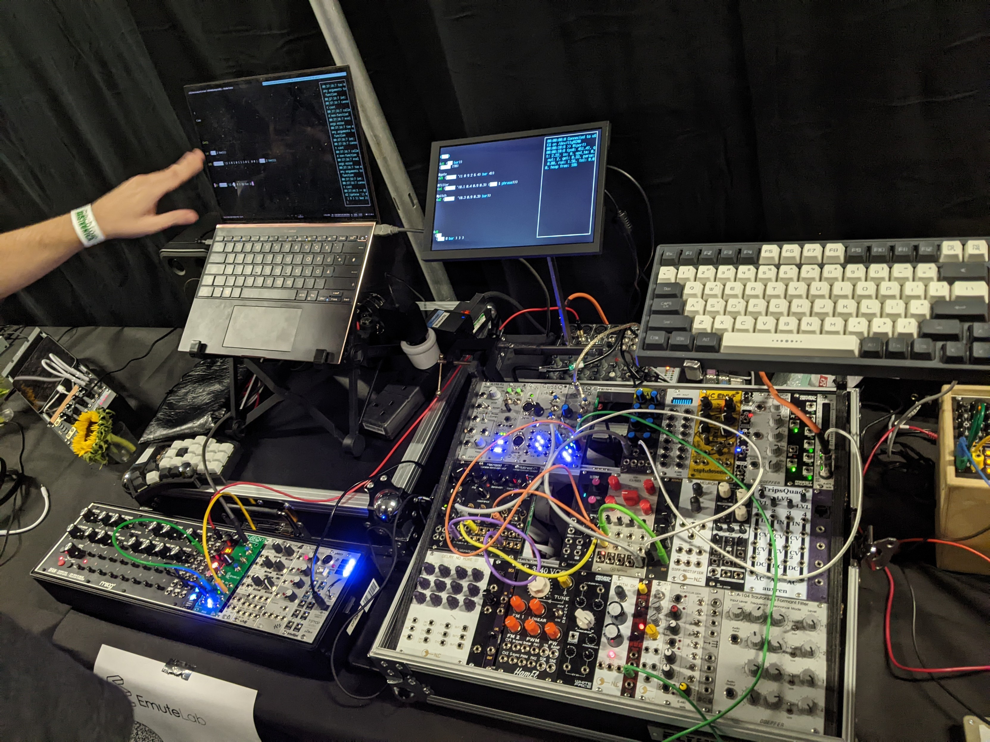
uSEQ modules set up within eurorack performance systems
More info from https://www.emutelabinstruments.co.uk/useq/
The firmware/language specs live in docs/specs/MAIN.md. Protocol details live in docs/specs/wire-protocol.md.
The firmware is in the uSEQ folder.
Build the firmware in Arduino IDE, using the Earle Philhower Pico core.
| Setting | Value |
|---|---|
| Board | Generic RP2040 |
| Boot Stage 2 | W25Q080 QSPI /2 |
| Flash Size | 8MB (Sketch 1MB, FS: 7MB) |
| CPU Speed | 250MHz (Overclock) |
| Optimize | Optimize Even More (-O3) |
Overclock the Pico at 250Mhz and set the optimisation level to -O3.
We welcome pull requests.
| Qty | Value | Footprint | References |
|---|---|---|---|
| 13 | 100n | Capacitor_SMD:C_0603_1608Metric | C19, C22, C23, C25, C26, C29, C30, C31, C32, C39, C40, C41, C42 |
| 11 | 100n | Capacitor_SMD:C_0402_1005Metric | C10, C11, C14, C16, C17, C18, C20, C21, C24, C33, C37 |
| 10 | 100k | Resistor_SMD:R_0402_1005Metric | R1, R2, R4, R5, R7, R8, R9, R10, R11, R12 |
| 7 | 1k | Resistor_SMD:R_0402_1005Metric | R29, R59, R60, R61, R62, R63, R64 |
| 6 | 47k | Resistor_SMD:R_0603_1608Metric | R50, R51, R52, R53, R54, R55 |
| 6 | 5.1k 1% | Resistor_SMD:R_0402_1005Metric | R16, R17, R19, R20, R67, R68 |
| 5 | 18k | Resistor_SMD:R_0603_1608Metric | R23, R24, R33, R34, R35 |
| 5 | 9.1k | Resistor_SMD:R_0603_1608Metric | R25, R26, R27, R28, R32 |
| 4 | TL072 | Package_SO:SO-8_3.9x4.9mm_P1.27mm | U2, U8, U9, U10 |
| 3 | 1.5k | Resistor_SMD:R_0603_1608Metric | R31, R37, R65 |
| 3 | 10k | Resistor_SMD:R_0603_1608Metric | R41, R42, R43 |
| 3 | 10n | Capacitor_SMD:C_0402_1005Metric | C34, C35, C36 |
| 3 | 10u | Capacitor_SMD:C_0603_1608Metric | C9, C13, C38 |
| 3 | 12k | Resistor_SMD:R_0603_1608Metric | R38, R39, R40 |
| 3 | 27k | Resistor_SMD:R_0603_1608Metric | R56, R57, R58 |
| 3 | 33k | Resistor_SMD:R_0603_1608Metric | R44, R45, R46 |
| 3 | 51k | Resistor_SMD:R_0603_1608Metric | R47, R48, R49 |
| 3 | CJ431 SOT-23 | Package_TO_SOT_SMD:SOT-23 | U5, U6, U12 |
| 2 | 1.8, >24mW | Resistor_SMD:R_0603_1608Metric | R15, R66 |
| 2 | 100k | Eurocad:Alpha9mmPot | RV1, RV2 |
| 2 | 1N4148W | Diode_SMD:D_SOD-123 | D1, D2 |
| 2 | 1N5819 | Diode_SMD:D_SOD-323 | D3, D4 |
| 2 | 1nF | Capacitor_SMD:C_0402_1005Metric | C6, C7 |
| 2 | 1u | Capacitor_SMD:C_0402_1005Metric | C12, C15 |
| 2 | 1u | Capacitor_SMD:C_0603_1608Metric_Pad1.08x0.95mm_HandSolder | C1, C5 |
| 2 | 22u | Capacitor_SMD:C_0805_2012Metric | C3, C4 |
| 2 | 22u 0805 | Capacitor_SMD:C_0805_2012Metric_Pad1.18x1.45mm_HandSolder | C2, C8 |
| 2 | 27 | Capacitor_SMD:C_0402_1005Metric | R21, R22 |
| 2 | 30p | Capacitor_SMD:C_0402_1005Metric | C27, C28 |
| 2 | 33k | Resistor_SMD:R_0402_1005Metric | R13, R14 |
| 2 | 5.1k | Resistor_SMD:R_0402_1005Metric | R3, R6 |
| 2 | 5V reference | TestPoint:TestPoint_Pad_1.5x1.5mm | TP3, TP9 |
| 2 | B3U-1000P | digikey-footprints:Switch_Tactile_SMD_B3U-1000P | S1, S2 |
| 2 | Conn_02x01 | Connector_PinHeader_2.54mm:PinHeader_1x02_P2.54mm_Vertical | J7, J8 |
| 2 | FerriteBead GZ2012D101TF | Resistor_SMD:R_0805_2012Metric | FB1, FB2 |
| 2 | MMBT3904 | Package_TO_SOT_SMD:SOT-23 | Q1, Q2 |
| 2 | TLV76733DRVR | Package_SON:WSON-6-1EP_2x2mm_P0.65mm_EP1x1.6mm_ThermalVias | U1, U4 |
| 1 | -5V Ref | TestPoint:TestPoint_Pad_1.5x1.5mm | TP4 |
| 1 | 1V1 | TestPoint:TestPoint_Pad_1.5x1.5mm | TP8 |
| 1 | 1k | Resistor_SMD:R_0603_1608Metric | R36 |
| 1 | 4.7k | Resistor_SMD:R_0603_1608Metric | R18 |
| 1 | Analog Power | TestPoint:TestPoint_Pad_1.5x1.5mm | TP2 |
| 1 | CV In 1 | Connector_Audio:Jack_3.5mm_QingPu_WQP-PJ398SM_Vertical_CircularHoles | J4 |
| 1 | CV In 2 | Connector_Audio:Jack_3.5mm_QingPu_WQP-PJ398SM_Vertical_CircularHoles | J5 |
| 1 | CV Out | TestPoint:TestPoint_Pad_1.5x1.5mm | TP6 |
| 1 | CVIn | TestPoint:TestPoint_Pad_1.5x1.5mm | TP5 |
| 1 | DNF | Capacitor_SMD:C_0805_2012Metric | R30 |
| 1 | Digital Out | TestPoint:TestPoint_Pad_1.5x1.5mm | TP7 |
| 1 | Gate In 1 | Connector_Audio:Jack_3.5mm_QingPu_WQP-PJ398SM_Vertical_CircularHoles | J2 |
| 1 | Gate In 2 | Connector_Audio:Jack_3.5mm_QingPu_WQP-PJ398SM_Vertical_CircularHoles | J3 |
| 1 | Hanbo_USB_C_Receptacle_USB2.0_MC-110LD-L137 | emutelab:USB-C-TH_MC-110LD-L137-A | J1 |
| 1 | LED A1 | LED_THT:LED_D3.0mm_FlatTop | D7 |
| 1 | LED A2 | LED_THT:LED_D3.0mm_FlatTop | D8 |
| 1 | LED A3 | LED_THT:LED_D3.0mm_FlatTop | D11 |
| 1 | LED CV In 1 | LED_THT:LED_D3.0mm_FlatTop | D9 |
| 1 | LED CV In 2 | LED_THT:LED_D3.0mm_FlatTop | D10 |
| 1 | LED D1 | LED_THT:LED_D3.0mm_FlatTop | D12 |
| 1 | LED D2 | LED_THT:LED_D3.0mm_FlatTop | D13 |
| 1 | LED D3 | LED_THT:LED_D3.0mm_FlatTop | D14 |
| 1 | LED Gate In 1 | LED_THT:LED_D3.0mm_FlatTop | D5 |
| 1 | LED Gate In 2 | LED_THT:LED_D3.0mm_FlatTop | D6 |
| 1 | LED Test | LED_SMD:LED_0603_1608Metric | D15 |
| 1 | MCP6002-xMS | Package_SO:MSOP-8_3x3mm_P0.65mm | U3 |
| 1 | Out A1 | Connector_Audio:Jack_3.5mm_QingPu_WQP-PJ398SM_Vertical_CircularHoles | J9 |
| 1 | Out A2 | Connector_Audio:Jack_3.5mm_QingPu_WQP-PJ398SM_Vertical_CircularHoles | J10 |
| 1 | Out A3 | Connector_Audio:Jack_3.5mm_QingPu_WQP-PJ398SM_Vertical_CircularHoles | J11 |
| 1 | Out D1 | Connector_Audio:Jack_3.5mm_QingPu_WQP-PJ398SM_Vertical_CircularHoles | J12 |
| 1 | Out D2 | Connector_Audio:Jack_3.5mm_QingPu_WQP-PJ398SM_Vertical_CircularHoles | J13 |
| 1 | Out D3 | Connector_Audio:Jack_3.5mm_QingPu_WQP-PJ398SM_Vertical_CircularHoles | J14 |
| 1 | PIN_HEADER_2x5 POWER | Connector_PinHeader_2.54mm:PinHeader_2x05_P2.54mm_Vertical_SMD | H1 |
| 1 | RP2040 | emutelab:RP2040-QFN-56 | U7 |
| 1 | RP2040 Power | TestPoint:TestPoint_Pad_1.5x1.5mm | TP1 |
| 1 | SWD | Connector_PinHeader_2.54mm:PinHeader_1x03_P2.54mm_Vertical | J15 |
| 1 | SW_Push | mouser:GPBS850N | SW1 |
| 1 | SW_SPDT | emutelab:Thonk DWB2 | SW3 |
| 1 | W25Q128JVS | Package_SO:SOIC-8_5.23x5.23mm_P1.27mm | U11 |
| 1 | YXC X322512MSB4SI | Crystal:Crystal_SMD_3225-4Pin_3.2x2.5mm | Y1 |
Emute-Lab-Instruments/uSEQ
Hardware & firmware of the uSEQ Live Coding CV & Gate Sequencer

Emute-Lab-Instruments/uSEQ
Hardware & firmware of the uSEQ Live Coding CV & Gate Sequencer

Vishalbabu-09/Auralab_Workstation
Advanced 4-layer PCB design featuring split-plane noise isolation (AGND/DGND) and asynchronous dual-core processing. Implements a handheld multi-tool oscilloscope, current tracker, and symmetrical DC power supply.


embeddedos-org/eCAD-Hardware-Products
Hardware designs + EE docs + Board datasheets of Multiple products

schenkmi/electronic-projects
misc electronic projects

WURocketry/Electrical_2023-2024
Electrical Repository for 2023-2024 Competition Year

antmicro/programmable-led-panel
LED matrix controlled with iCE40 FPGA or RP2040 MCU for benchmarking and integration of video systems

antmicro/audio-latency-tester-board
This project contains open hardware design files for an audio latency processing board. The system allows driving an external speaker and collecting audio samples from a pair of PDM or I2S microphones.

alph4345/test
TrinketCore puts everything a small rechargeable gadget needs on one 40 × 60 mm board, ready to order assembled from PCBWay:
It measures 40.6 × 108 mm and has 2 copper layers, 1.6 mm thick.
172 parts, built around the RP2040, TL072, W25Q128JVSIQ and TLV76733DRVR. The full list of its parts is on this page, with links to each part's symbol and footprint where PCBKit's library has them.
From the Emute-Lab-Instruments/uSEQ repository on GitHub, at the commit this page was made from: the board is hardware/version1.0/useq1/useq1.kicad_pcb and its schematic hardware/uSeqIns1.0/uSeqIns1.0.kicad_sch. PCBKit opens the board in the browser, with nothing to install.
Its repository states no licence, so its author keeps all rights: ask Emute-Lab-Instruments before reusing the design.