
2 layers160 × 100 mm

 ETAChalmers/Discosoffa
Repo för allt vad gäller den fabulösa Discosoffan!
Motor driver is an open-source printed circuit board by ETAChalmers, from the ETAChalmers/Discosoffa repository on GitHub. It is a 2-layer board of 231.6 × 160 mm with 156 parts on 96 nets, routed with 556 tracks and 6 vias.
It is built around the NE555. Its parts include 64 resistors, 50 transistors, 21 capacitors, 8 connectors and 7 diodes. It belongs with the robots and motor control boards of this library.
Repo för allt vad gäller den fabulösa Discosoffan!
Det BMS (Battery Management System) vilket används på soffan är Jonathan Locks egendesignade Modular BMS-projekt. PCB-design, kod samt dokumentation för dessa finns att tillgå från hans GitLab repository.
Discosoffans batteripack är på 5-celler seriellt (5S). För detta behövs en modul per cell, varav en är master.
Följande är de konfigurationer Discosoffans BMS-moduler använder. Dessa anges i config.h.
/** @brief Voltage which gives 100%-active discharge output [volt]
 * Voltages above this value will also keep the discharge output fully on */
#define VTHRS_DISCH_MAX_V				4.00

/** @brief Voltage which gives 0%-active discharge output [volt]
 * Voltages below this value will also keep the discharge output fully off */
#define VTHRS_DISCH_MIN_V				3.95

/** @brief Threshold voltage for activating the charge-disable output [volt] */
#define VTHRS_CHGDIS_START_V			4.05

/** @brief Threshold voltage for de-activating the charge-disable output [volt] */
#define VTHRS_CHGDIS_STOP_V				4.00

/** @brief Threshold voltage for triggering an undervoltage alarm [volt]
 * See also TMIN_UV_ALARM_S */
#define VTHRS_UV_ALARM_V				3.50

/** @brief Threshold voltage for triggering an overvoltage alarm [volt] */
#define VTHRS_OV_ALARM_V				4.10

/** @brief Voltage hysteresis for leaving alarm state [volt]
 * To leave the undervoltage alarm the sampled voltage must exceed
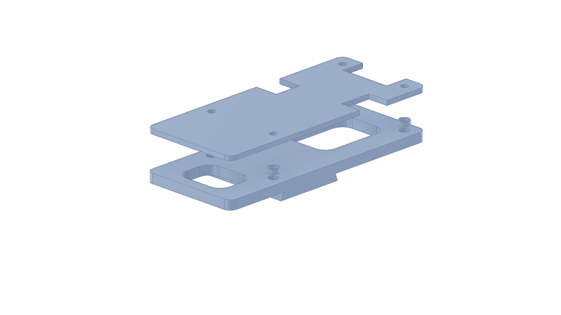
* VTHRS_UV_ALARM_V + VHYST_ALARMS_V, and to leave the overvoltageBMS-modulerna är monterade i 3D-printade hållare. 3D STEP-filerna till dessa finns i bms_box. Dessa ser ut som nedan:
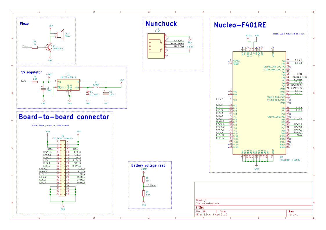
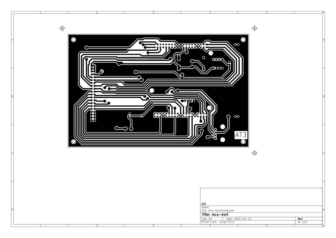
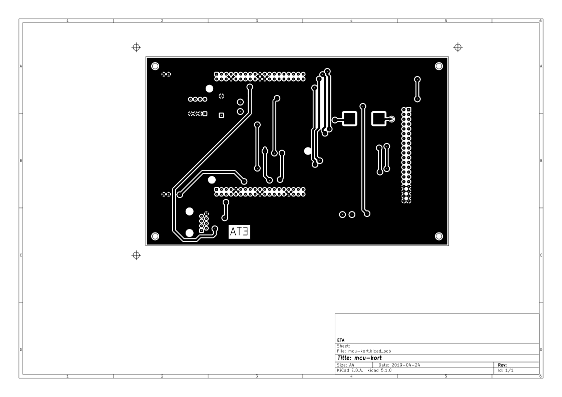
Kortet vilket sköter styrningen av soffan. Denna huserar en Nucleo-F401RE dev board.
| Qty | Value | Footprint | References |
|---|---|---|---|
| 32 | Q_NMOS_GDS | TO_SOT_Packages_THT:TO-220-3_Horizontal_Reversed | Q201, Q202, Q205, Q206, Q207, Q208, Q211, Q212, Q401, Q402, Q405, Q406, Q407, Q408, Q411, Q412 +16 |
| 27 | 1k | Resistors_SMD:R_0603_HandSoldering | R201, R205, R206, R209, R216, R217, R301, R303, R304, R401, R405, R406, R409, R416, R417, R501 +11 |
| 16 | 10k | Resistors_SMD:R_0603_HandSoldering | R203, R204, R211, R212, R403, R404, R411, R412, R503, R504, R511, R512, R603, R604, R611, R612 |
| 16 | Q_NPN_BEC | TO_SOT_Packages_SMD:SOT-23 | Q203, Q204, Q209, Q210, Q403, Q404, Q409, Q410, Q503, Q504, Q509, Q510, Q603, Q604, Q609, Q610 |
| 8 | 40k | Resistors_SMD:R_0603_HandSoldering | R207, R208, R407, R408, R507, R508, R607, R608 |
| 4 | 100k | Resistors_SMD:R_0603_HandSoldering | R210, R410, R510, R610 |
| 4 | 100m | Capacitors_THT:CP_Radial_D8.0mm_P3.50mm | C202, C402, C502, C602 |
| 4 | 100n | Capacitors_SMD:C_0603_HandSoldering | C203, C403, C503, C603 |
| 4 | 100p | Capacitors_SMD:C_0603_HandSoldering | C204, C404, C504, C604 |
| 4 | 10n | Capacitors_SMD:C_0603_HandSoldering | C201, C401, C501, C601 |
| 4 | 220R | Resistors_SMD:R_0603_HandSoldering | R215, R415, R515, R615 |
| 4 | 3V3 | Diodes_THT:D_DO-35_SOD27_P5.08mm_Vertical_AnodeUp | D201, D401, D501, D601 |
| 4 | CONN_01X02 | Connectors:AK300-2 | J201, J401, J501, J601 |
| 4 | Opamp_Dual_Generic | SMD_Packages:SOIC-8-N | U201, U401, U501, U601 |
| 4 | R_Shunt | footprints:10uOhmShunt | R202, R402, R502, R602 |
| 3 | CONN_01X02 | footprints:TerminalBlock-XXL | J102, J103, J104 |
| 3 | D | Diodes_THT:D_T-1_P5.08mm_Horizontal | D301, D302, D303 |
| 2 | 220m | Capacitors_THT:CP_Radial_D25.0mm_P10.00mm_SnapIn | C101, C102 |
| 2 | Q_NPN_BEC | TO_SOT_Packages_SMD:SOT-23_Handsoldering | Q301, Q302 |
| 1 | 100u | Capacitors_THT:CP_Radial_D5.0mm_P2.50mm | C302 |
| 1 | 10u | Capacitors_THT:CP_Radial_D5.0mm_P2.00mm | C303 |
| 1 | 150k | Resistors_SMD:R_0603_HandSoldering | R302 |
| 1 | 1n | Capacitors_SMD:C_0603_HandSoldering | C301 |
| 1 | CONN_02X20 | Connectors_IDC:IDC-Header_2x20_Pitch2.54mm_Straight | J101 |
| 1 | LM7810ACT | TO_SOT_Packages_THT:TO-220_Horizontal | U302 |
| 1 | NE555 | SMD_Packages:SOIC-8-N | U301 |


leomil72/LM80C
A Z80-based homebrew computer withTMS9918, AY-3-8910, Z80 CTC, Z80 PIO, and Z80 SIO

DoctorWkt/CSCvon8
A crazy small 8-bit CPU built with only seventeen 7400-series chips.

nicolacimmino/PLC-14500
Retro trainer board based on the MC14500 1-bit ICU. The project is OSHW certified and a ready to assemble kit is available on Tindie.

bvarner/pi485
An open-source TTL UART <-> RS485 converter, intended for a Raspberry Pi or Arduino

kraakenstuff/ADSR
2HP ADSR module based on "Fastest Envelope in the West" by René Schmitz (https://www.schmitzbits.de/adsr.html)
It measures 231.6 × 160 mm and has 2 copper layers, 1.6 mm thick.
156 parts, built around the NE555. The full list of its parts is on this page, with links to each part's symbol and footprint where PCBKit's library has them.
From the ETAChalmers/Discosoffa repository on GitHub, at the commit this page was made from: the board is electronics/motor_driver/motor_driver.kicad_pcb. PCBKit opens the board in the browser, with nothing to install.
Its repository states no licence, so its author keeps all rights: ask ETAChalmers before reusing the design.