2 layers231.3 × 96.5 mm

 DoctorWkt/CSCvon8112
A crazy small 8-bit CPU built with only seventeen 7400-series chips.
CSCvon8 is an open-source printed circuit board by DoctorWkt, from the DoctorWkt/CSCvon8 repository on GitHub, published under the GPL-3.0 licence. It is a 2-layer board of 249.9 × 89.4 mm with 55 parts on 136 nets, routed with 2,041 tracks and 34 vias.
It is built around the UM245R, AT27C1024-70PU and 74HCT574D, with the 74HCT04D, 74HCT138D and 74HCT139D among its other parts. Its parts include 21 capacitors, 19 ICs, 7 connectors, 5 resistors and 2 switches. It belongs with the retro computing and games boards of this library.


This repository holds the files for my 8-bit "big brother" CPU to the 4-bit Crazy Small CPU. This is a von Neumann style CPU designed with 7400-style logic chips, 32K of RAM, 32K of ROM and a UART. The CPU requires only seventeen chips, not including the clock circuitry. A short video is here.
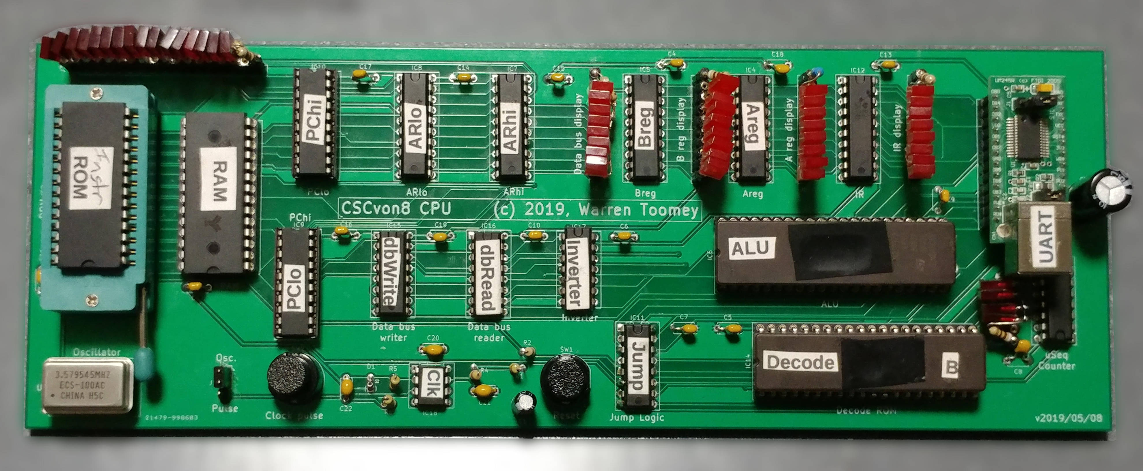
The overall design of the CPU is covered in Docs/CSCvon8_design.md. Also read the getting started guide and the guide to building the PCB version.
As at the 18th May 2019 I have the CPU running solidly at 3.57MHz on the PCBs that I ordered from the PCB design in the Schematics folder. I've kept a journal with details of my progress from the initial design phase through to the successful build.
The files and folders in this repository are:
There is also a Verilog version with the top-level file being ttlcsvon8.v, the testbench is icarus_tb.v and the Makefile will build and run the Verilog testbench. Some notes on this implementation are in the Docs/implementation_notes.md file.
| Qty | Value | Footprint | References |
|---|---|---|---|
| 19 | 0.1uF | Capacitors_THT:C_Disc_D4.7mm_W2.5mm_P5.00mm | C4, C5, C6, C10, C11, C12, C13, C14, C15, C16, C17, C18, C19, C20, C21, C22 +3 |
| 5 | 74HCT574 | Housings_DIP:DIP-20_W7.62mm_Socket | IC4, IC5, IC7, IC8, IC12 |
| 2 | 10K | Resistors_THT:R_Axial_DIN0204_L3.6mm_D1.6mm_P1.90mm_Vertical | R5, R6 |
| 2 | 74LS593 | Housings_DIP:DIP-20_W7.62mm_Socket | IC9, IC10 |
| 2 | SW_Push_Dual | Buttons_Switches_THT:Push_E-Switch_KS01Q01 | SW1, SW2 |
| 1 | 10uF | Capacitors_THT:CP_Radial_D5.0mm_P2.00mm | C1 |
| 1 | 1K | Resistors_THT:R_Axial_DIN0204_L3.6mm_D1.6mm_P1.90mm_Vertical | R2 |
| 1 | 1M | Resistors_THT:R_Axial_DIN0204_L3.6mm_D1.6mm_P1.90mm_Vertical | R4 |
| 1 | 1N4148 | Diodes_THT:D_DO-35_SOD27_P2.54mm_Vertical_AnodeUp | D1 |
| 1 | 20K | Resistors_THT:R_Axial_DIN0204_L3.6mm_D1.6mm_P1.90mm_Vertical | R1 |
| 1 | 220uF | Capacitors_THT:CP_Radial_D8.0mm_P5.00mm | C3 |
| 1 | 28C256 | Housings_DIP:DIP-28_W15.24mm_Socket | IC2 |
| 1 | 74HCT04 | Housings_DIP:DIP-14_W7.62mm_Socket | IC17 |
| 1 | 74HCT138 | Housings_DIP:DIP-16_W7.62mm_Socket | IC16 |
| 1 | 74HCT139 | Package_DIP:DIP-16_W7.62mm_Socket | IC15 |
| 1 | 74HCT151 | Package_DIP:DIP-16_W7.62mm_Socket | IC11 |
| 1 | 74HCT161 | Housings_DIP:DIP-16_W7.62mm_Socket | IC13 |
| 1 | AS6C62256 | Housings_DIP:DIP-28_W15.24mm_Socket | IC1 |
| 1 | AT27C1024-70PU | Housings_DIP:DIP-40_W15.24mm_Socket | IC14 |
| 1 | Address Bus Pin Header | Connector_PinSocket_2.54mm:PinSocket_1x18_P2.54mm_Vertical | J3 |
| 1 | Areg Pin Header | Connector_PinSocket_2.54mm:PinSocket_1x10_P2.54mm_Vertical | J6 |
| 1 | Breg Pin Header | Connector_PinSocket_2.54mm:PinSocket_1x10_P2.54mm_Vertical | J7 |
| 1 | Data Bus Pin Header | Connector_PinSocket_2.54mm:PinSocket_1x10_P2.54mm_Vertical | J2 |
| 1 | ECS-100A-035 | QX14T50B1.843200B50TT:QX14T50B1.843200B50TT | U1 |
| 1 | IR Pin Header | Connector_PinSocket_2.54mm:PinSocket_1x10_P2.54mm_Vertical | J5 |
| 1 | Jumper_3_Bridged12 | Connector_PinSocket_2.54mm:PinSocket_1x03_P2.54mm_Vertical | J1 |
| 1 | M27C322-100F1 | Housings_DIP:DIP-42_W15.24mm_Socket | IC6 |
| 1 | NE555 | Housings_DIP:DIP-8_W7.62mm_Socket | IC18 |
| 1 | UM245R | Housings_DIP:DIP-24_W15.24mm_Socket | IC3 |
| 1 | uSeq Pin Header | Connector_PinSocket_2.54mm:PinSocket_1x06_P2.54mm_Vertical | J4 |


leomil72/LM80C
A Z80-based homebrew computer withTMS9918, AY-3-8910, Z80 CTC, Z80 PIO, and Z80 SIO

flypie/Gigatron
This is a version of the files from https://gigatron.io/ altered to work on a vanilla KiCAD 5.1.6. Changes are minimal in the schematic and PCB, layout has only been changed where dimensions or orientations changed as a…


ksr/p8x
Generated by generators/genkicad.py from the canonical geneagle netlist (CARDS["peripheral-card"]), same standard as the memory card: 4-layer (F/B signals, In1=GND, In2=VCC planes), a bypass cap above each IC, a…
It measures 249.9 × 89.4 mm and has 2 copper layers, 1.6 mm thick.
55 parts, built around the UM245R, AT27C1024-70PU, 74HCT574D and 74HCT04D. The full list of its parts is on this page, with links to each part's symbol and footprint where PCBKit's library has them.
From the DoctorWkt/CSCvon8 repository on GitHub, at the commit this page was made from: the board is Schematic/Schematic.kicad_pcb. PCBKit opens the board in the browser, with nothing to install.
Its repository publishes it under the GPL-3.0 licence: you may reuse it on that licence's terms (keep the author's notice, and for a copyleft licence share your changes alike).