

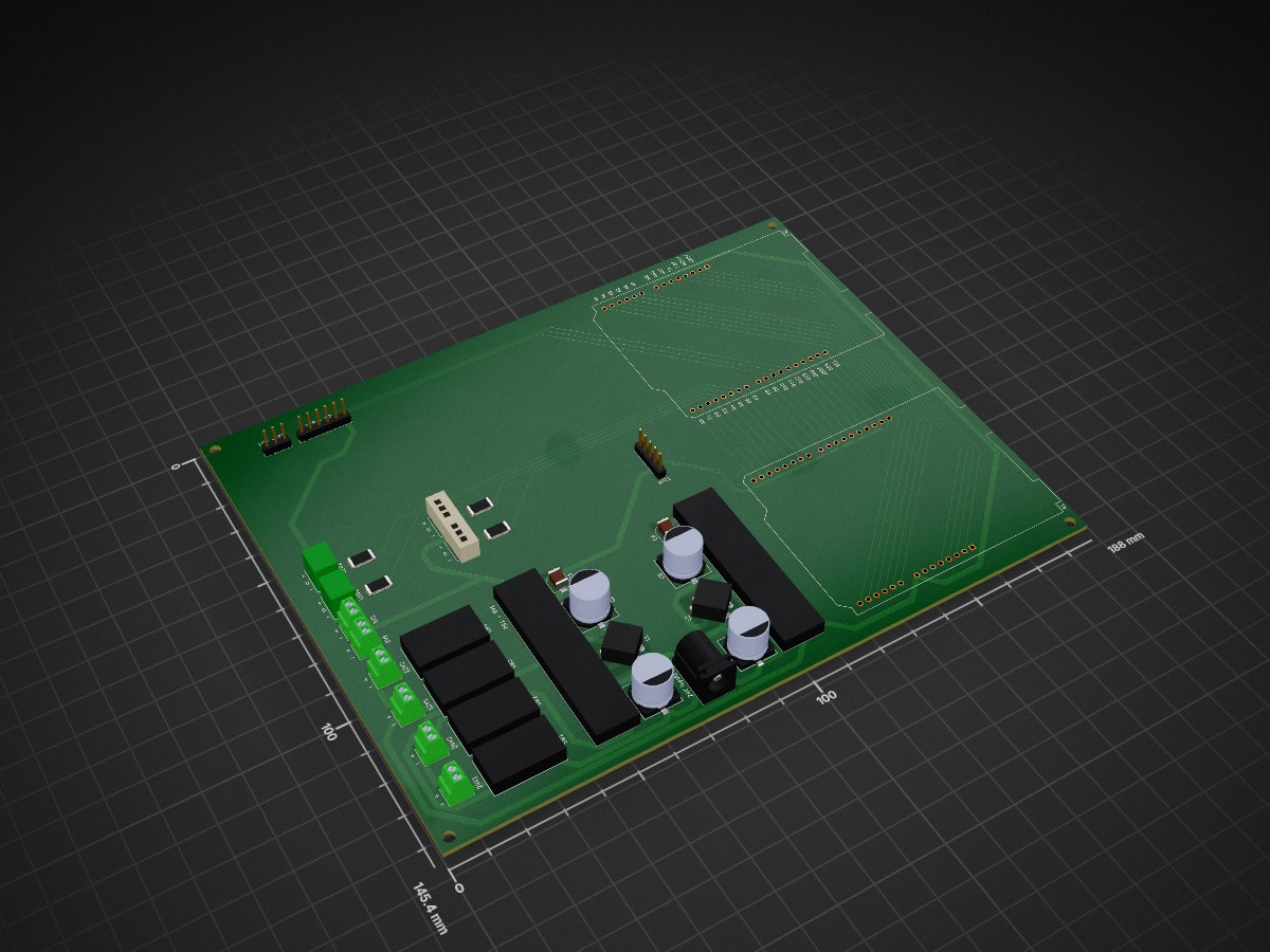
Sleep rig pcb
- Size
- 188 × 145.4 mm
- Copper layers
- 2
- Thickness
- 1.6 mm
- Parts
- 34
- Nets
- 54
- Pads
- 167
- Tracks, vias
- 283, 0
- Pours
- 1
- Routed
- Yes
- KiCad
- KiCad 7 (file 20221018)
- Created
- 20 Feb 2024
- Updated
- 11 Oct 2024
Overview
Sleep rig pcb is an open-source printed circuit board by EPL-Engineering, from the EPL-Engineering/sleep_rig repository on GitHub. It is a 2-layer board of 188 × 145.4 mm with 34 parts on 54 nets, routed with 283 tracks and 0 vias.
It is built around the ARDUINO UNO R3, NID100-12 and NID100-5, with the L101011MS02Q, RPC2512JT220R and CMS1-4-R among its other parts. Its parts include 6 capacitors, 4 resistors, 4 switches, 2 connectors and 2 inductors. It belongs with the AVR (ATmega, ATtiny) boards of this library.
Main components
8ARDUINO UNO R3
Arduino UNO R3 Printed Circuit Board ModuleArduinoUncategorisedNID100-12
SIP,50.8x12mm1 12V 20V~53V 7.5A 96% SIP,50.8x12mm Power Module/Power Supply ROHSMWDC-DC Power ModulesNID100-5
-- Power Module/Power Supply ROHSMWPower Module/Power SupplyL101011MS02Q
插件-30℃~+65℃ 28V Rectangular Columnar SPST Through Hole 插件 Slide Switches ROHSC&KSlide SwitchesRPC2512JT220R
2512-55℃~+155℃ 1.5W 220Ω Thick Film Resistor ±100ppm/℃ ±5% 2512 Chip Resistor - Surface Mount ROHSStackpole Electronics (SEI)Chip Resistor - Surface MountCMS1-4-R
SMD-4P,9.4x7.2mm-40℃~+160℃ 18uH@100kHz 2 3.8A 300V 8.9mΩ SMD-4P,9.4x7.2mm Common Mode Filters ROHSEatonCommon Mode FiltersEEEFK1V220R
SMD,D5xL5.8mm-55℃~+105℃ 120mA@120Hz 2000hrs@105℃ 22uF 35V 5mm 6.1mm Polarized ±20% SMD,D5xL5.8mm Aluminum Electrolytic Capacitors - SMD ROHSPanasonicAluminum Electrolytic Capacitors - SMDPJ-002BH
插件-25℃~+85℃ 2.5mm 24V 5A 6.5mm DC Power Jack Right Angle 插件 DC Power Connectors ROHSCUIDC Power Connectors
README
README.mdEnvironment Monitor
TODO
- Save state across serial reconnects (desolder RST ENABLE)
- Finish chart display for log data
- Cleanup upon application exit
Hardware Setup
- Plug in the red/yellow/black climate sensor cables to the 3-pin molex connectors on the PCB (DHT1 and DHT2 labels on PCB)
- Using a precision flathead, screw the wires from the LED strips into the terminal blocks of the PCB (LED1 and LED2 labels on PCB)
- Red wire goes to '+' terminal
- Black wire goes to '-' terminal
- Colored wire (blue/green) goes to 'D' terminal
- Connecting the wires in the wrong configuration will fry the entire LED strip
- Optional: connect the positive and negative leads of the box fan to either the 24V or 12V onboard switches, depending on fan specs
- Double check all of your connections and make sure the positive and negative terminals are always hooked up to a red and black wire, respectively
- Plug in 24V power source to the barrel jack on the PCB (DO NOT PLUG 24V INTO THE ARDUINO BARREL JACK — ONLY USE ONBOARD JACK)
- Plug USB-B into the Arduino and connect other end to PC where GUI is running
Connecting to Serial
- Run EnvironmentMonitor.exe located in the main folder of this repo
- Select the COM port that is tied to the Arduino and click connect
- Arduino will reset all settings when the serial connection is reconnected
- Arduino is ready when "SER_CON" event is pinged back
Auto LED Timer
- Specify a day start and day stop time in 24HR clock format (make sure day start comes before day end chronologically, or bugs may occur)
- Simply click start to initiate the day/night cycling (white light starts at day start time and red light at day end)
- Click stop at any time to cancel the day/night cycling and turn of the LEDs (do this before disconnecting the serial port)
Manual Color Control
- Select color and click send to manually control LED color; LEDs will behave according to most recent data sent (e.g. manual control will change the color even when day/night cycle is running)
- Enter integer number between 0-255 to adjust the brightness of both LED strips; brightness setting is the same for both boxes despite two separate controls
Serial Monitor
- Every 15 minutes or upon any command entry, the Arduino will send a packet with sensor data from both boxes
- Data is formatted as a string and written to both a log.txt file inside the repo and the serial monitor display
- A new log file is opened upon serial connect; disconnecting serial or closing the window will save the file
- Log files will append an increasing integer to filename to avoid overwriting
Special Notes
- To avoid bugs, always disconnect the serial port before closing the application
- The Arduino will restart if it reconnects to serial, but it will continue running at disconnect (e.g. you can enable auto day/night cycles and it will continue to run if you disconnect serial port; it will reset and turn off when you reconnect to serial)
- Boxes can be run independently, but log entries will still track both
- Default brightness is set to 1; you will need to increase this
Parts
34| Qty | Value | Footprint | References |
|---|---|---|---|
| 4 | EEE-FN1J121UP | 120uF_cap:CAP_FN_G_PAN | C1, C2, C4, C5 |
| 4 | L101011MS02Q | switch:SW_1MS02Q_CNK | SW1, SW2, SW3, SW4 |
| 4 | RPC2512JT220R | smd_220_res:STA_RPC2512_STP | R1, R2, R3, R4 |
| 2 | 12V | terminal_block_bi:TE_282834-2 | 12V1, 12V2 |
| 2 | 5V | terminal_block_bi:TE_282834-2 | 5V1, 5V2 |
| 2 | Arduino_UNO_R3 | Module:Arduino_UNO_R3 | A1, A2 |
| 2 | CMS1-4-R | choke:CMS1 | L1, L2 |
| 2 | EEEFK1V220R | 22uF_cap:CAP_EEEFK1V220R | C3, C6 |
| 1 | DHT1 | molex_tri:MOLEX_0022272031 | DHT1 |
| 1 | DHT2 | molex_tri:MOLEX_0022272031 | DHT2 |
| 1 | FAN1 | terminal_block_bi:TE_282834-2 | 24V1 |
| 1 | FAN2 | terminal_block_bi:TE_282834-2 | 24V2 |
| 1 | LCD - P1 | Connector_PinHeader_2.54mm:PinHeader_1x03_P2.54mm_Vertical | LCD - P1 |
| 1 | LCD - P2 | Connector_PinHeader_2.54mm:PinHeader_1x06_P2.54mm_Vertical | LCD - P2 |
| 1 | LED1 | terminal_block_tri:CONN_282834-3_TYC | J4 |
| 1 | LED2 | terminal_block_tri:CONN_282834-3_TYC | J5 |
| 1 | NID100-12 | dc_regulator:CONV_NID100-5 | PS2 - 12V1 |
| 1 | NID100-5 | dc_regulator:CONV_NID100-5 | PS1 - 5V1 |
| 1 | PJ-002BH | barrel_jack:CUI_PJ-002BH | 24V Input1 |
| 1 | RTC | Connector_PinHeader_2.54mm:PinHeader_1x05_P2.54mm_Vertical | RTC1 |
Similar boards
- 4 layers249.5 × 95 mm
- 2 layers87.5 × 100 mm

PCB Ventil
reivax-boucoi/PCB_Kicad
Repo for all my home projects involving PCBs developped with Kicad
58 parts1 - 2 layers64.8 × 50.5 mm

- 6 layers92.6 × 69.4 mm

Usb hub 2
yedidia-sisay/usb3-multiport-hub
An open-source USB 3.2 Gen 2 (10 Gbps) multiport hub & docking station.
230 parts - 4 layers59.7 × 70 mm

- 2 layers60 × 60 mm

- 2 layers

- 2 layers63.9 × 89.2 mm

Ab rec
LJWsao/sinitsa
KiCAD files for the all band receiver. This can pick up strong local sources of RF such as AM and FM radio stations.
47 parts1
Questions
How big is the Sleep rig pcb PCB?
It measures 188 × 145.4 mm and has 2 copper layers, 1.6 mm thick.
What parts does the Sleep rig pcb use?
34 parts, built around the ARDUINO UNO R3, NID100-12, NID100-5 and L101011MS02Q. The full list of its parts is on this page, with links to each part's symbol and footprint where PCBKit's library has them.
Where can I download the Sleep rig pcb KiCad files?
From the EPL-Engineering/sleep_rig repository on GitHub, at the commit this page was made from: the board is hcam_environment_monitor_pcb/hcam_environment_monitor_pcb/sleep_rig_pcb.kicad_pcb and its schematic hcam_environment_monitor_pcb/hcam_environment_monitor_pcb/sleep_rig_pcb.kicad_sch. PCBKit opens the board in the browser, with nothing to install.
Can I use the Sleep rig pcb design in my own project?
Its repository states no licence, so its author keeps all rights: ask EPL-Engineering before reusing the design.