
2 layers155.9 × 107.2 mm
Bottom
DreaM117er/Paicorea
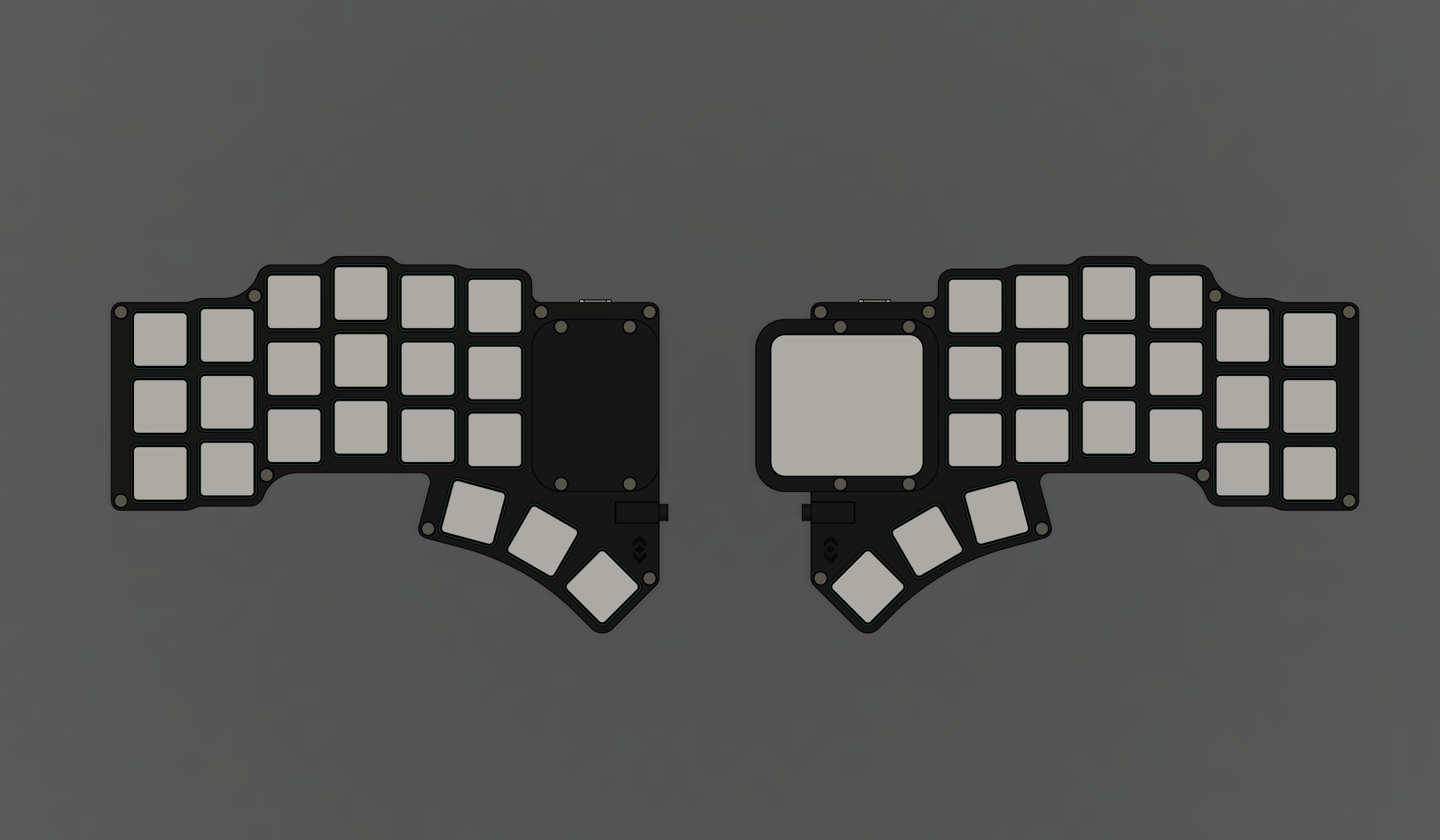
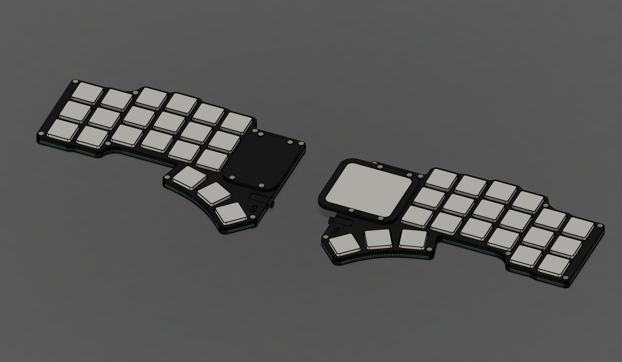
Paicorea is a 42 keys split keyboard, with optional way to drive Azoteq TPS43 trackpad.
8 parts29MIT

Paicorea is a 42 keys split keyboard, with optional way to drive Azoteq TPS43 trackpad.
File is an open-source printed circuit board by DreaM117er, from the DreaM117er/Paicorea repository on GitHub, published under the MIT licence. It is a 2-layer board of 155.9 × 107.2 mm with 74 parts on 66 nets, routed with 841 tracks and 99 vias.
It is built around the TPS43-201A-S and SK6805E-J. Its parts include 21 diodes, 21 switches, 6 inductors, 5 connectors and 4 resistors. It belongs with the keyboards and input boards and the RP2040 boards of this library.

 |  |
|---|---|
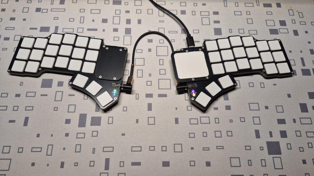 | 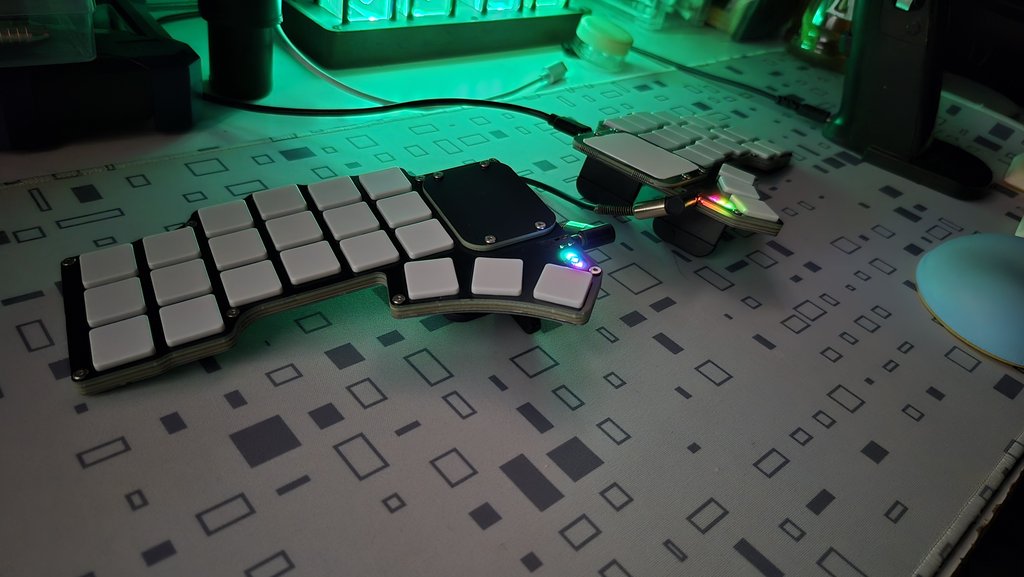 |
Paicorea是一把專門為我而設計的分離式機械鍵盤,目的是為了讓鍵盤可以達到極度輕薄,又可以搭載TPS43這張由Azoteq公司生產製造的觸控板,滿足我的日常生活而使用。
它可以根據自己的需求選擇是否觸控板作為滑鼠使用;鍵盤按鍵則是使用Kailh生產製造的PG1316S作為它「目前」的按鍵使用,往後不排除會設計另一種機械鍵軸的版本來給自己做使用。
鍵盤的最初設計是像AZCARD、Bayleaf、Makefive等一樣搭載PG1316S鍵軸的鍵盤都是以本體PCB作為底板壓縮厚度到3mm左右,但因為本人——也就是我自己,非常不喜歡使用無線設備(電池安全問題)的原因,一定得在鍵盤上搭載分離式鍵盤常見的3.5mm TRRS座,而我在這部分花了很多時間尋找能使用的零件,最後找到PJ-381B、PJ-381C、PJ-399等3款可以使用的沉板型號,再根據Datasheet跟3D設計,選擇了PJ-381B來使用。
在不想向下更換2.5mm TRRS座的前提下,很可惜地我只能將鍵盤厚度壓縮至5.5mm左右,但整體的結構讓我相當滿意。
使用RP2040 Core-A的原因——它跟用排線分離設計的RP2040-Tiny不同,我可以直接在PCB上拉USB2.0使用的USB-C口接線接在RP2040 Core-A上達到分離MCU跟USB-C的目的,而不用而外設計一個專門放置排線跟分離板的位置,而且又是厚度只有5.5mm的空間內。
最終從MCU——RP2040 Core-A(Raspberry Pi)中取Pi(π,Pai同音)、Core-A(corea),Paicorea就這麼誕生了。
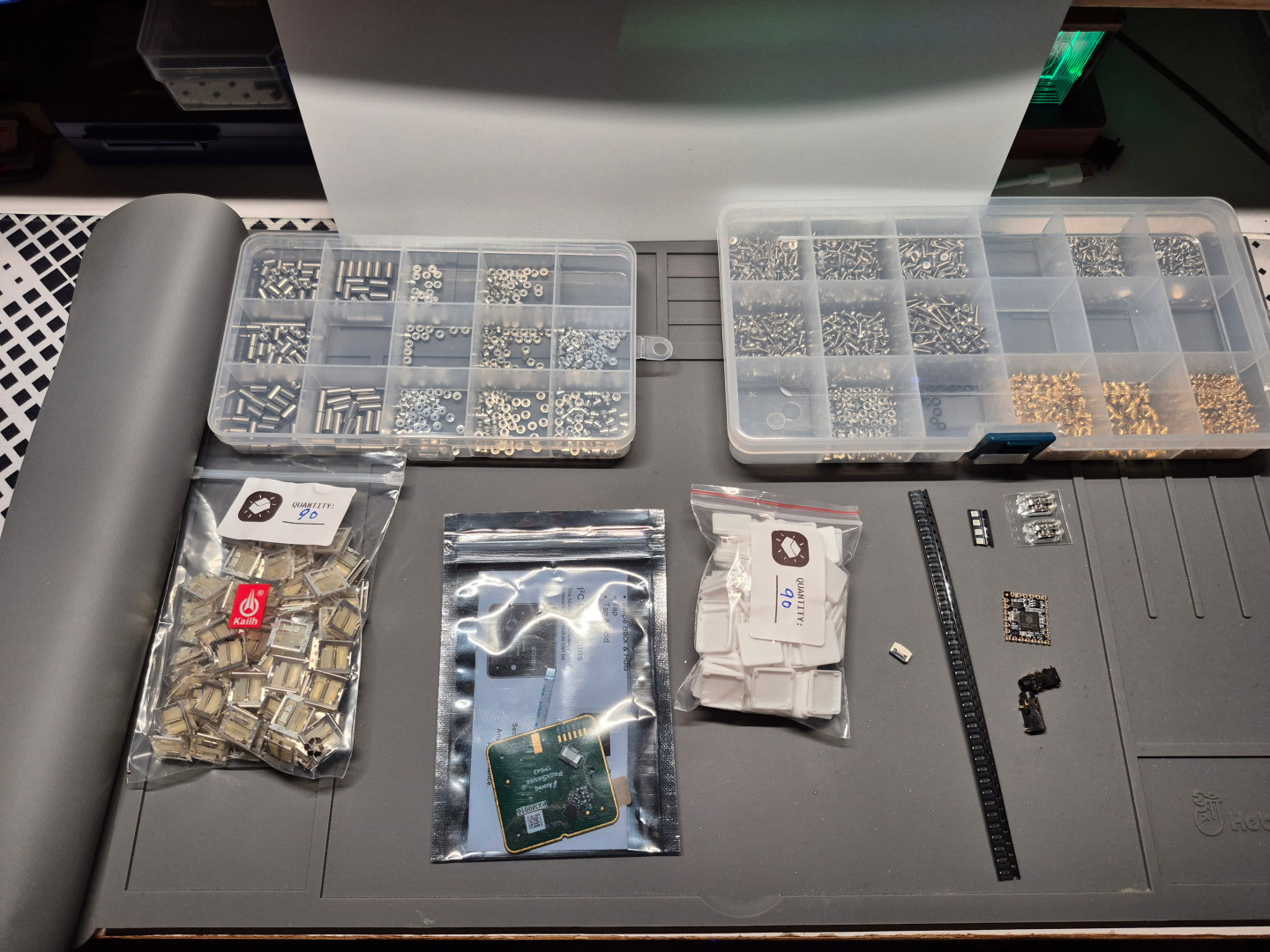
| 名稱 | 規格 | 數量 | 備註 |
|---|---|---|---|
| MCU | RP2040 Core-A | 2 | Aliexpress Link |
| Type-C母座 | TYPE-C 16P CB1.6 | 2 | 沉板1.6mm |
| TRRS母座 | PJ-381B | 2 | - |
| 二極體 | 1N4148 SOD-123 | 42 | - |
| 貼片電阻 | 5.1K、0603 | 4 | 焊接後可支援C2C |
| 鍵軸 | Kailh PG1316S | 42 | - |
| 鍵帽 | 適用PG1316S、1u大小 | 42 | 推薦用買的,3D列印需留意邊角圓弧 |
| 貼片銅柱 | MAC8 TH0.8-2.0-M2(2.0) | 16 | - |
| 貼片銅柱 | MAC8 TH1.6-2.0-M2(2.0) | 8 | - |
| M2螺絲 | 牙長5mm、頭部小於ø4.2mm | 24 | - |
| 矽膠自黏腳貼 | ø8mm、厚度0.5-1.0mm | - | 根據自己所需決定數量 |
| 緩衝墊 | 厚度0.5-0.8mm | - | 矽膠或Poron等緩衝材料;需要裁切大小,請自行判斷需要多大面積 |
| PVC板材 | 厚度0.8mm | - | 觸控板面用,A4大小即可,需要裁切 |
| 0.5mm FFC排線座 | 6Pin | 1 | 選配,安裝觸控板才需要 |
| 0.5mm FFC軟排線 | 6Pin、50mm、AA同向 | 1 | 選配,安裝觸控板才需要 |
| 觸控板 | Azoteq TPS43-201A-S | 1 | 選配 |
| 貼片LED燈 | SK6805-2427(Micro) | 6 | 選配,裝飾燈 |
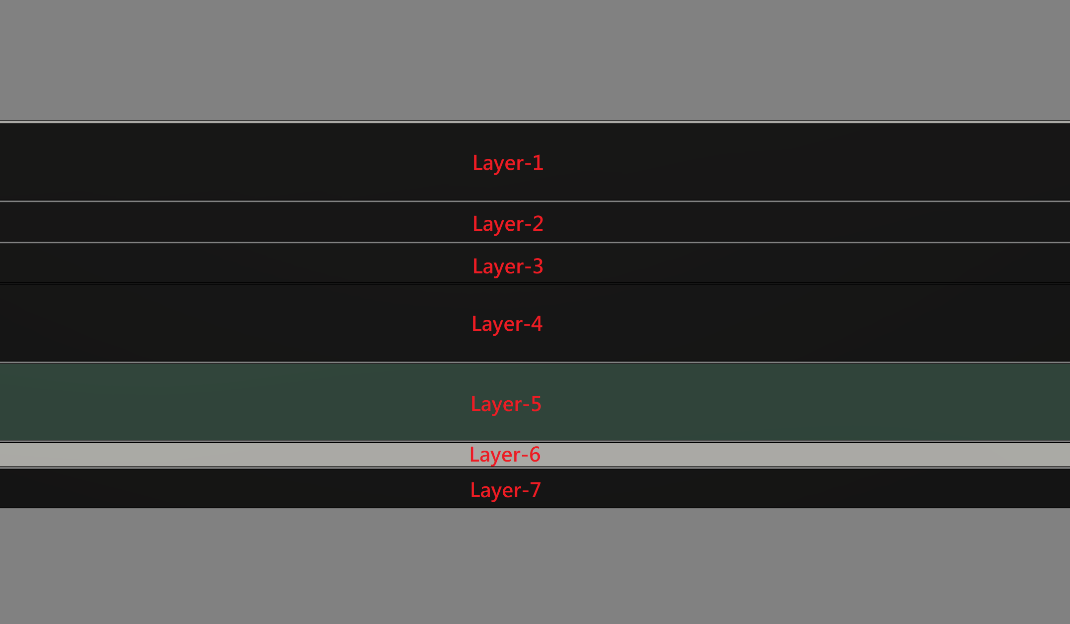 | 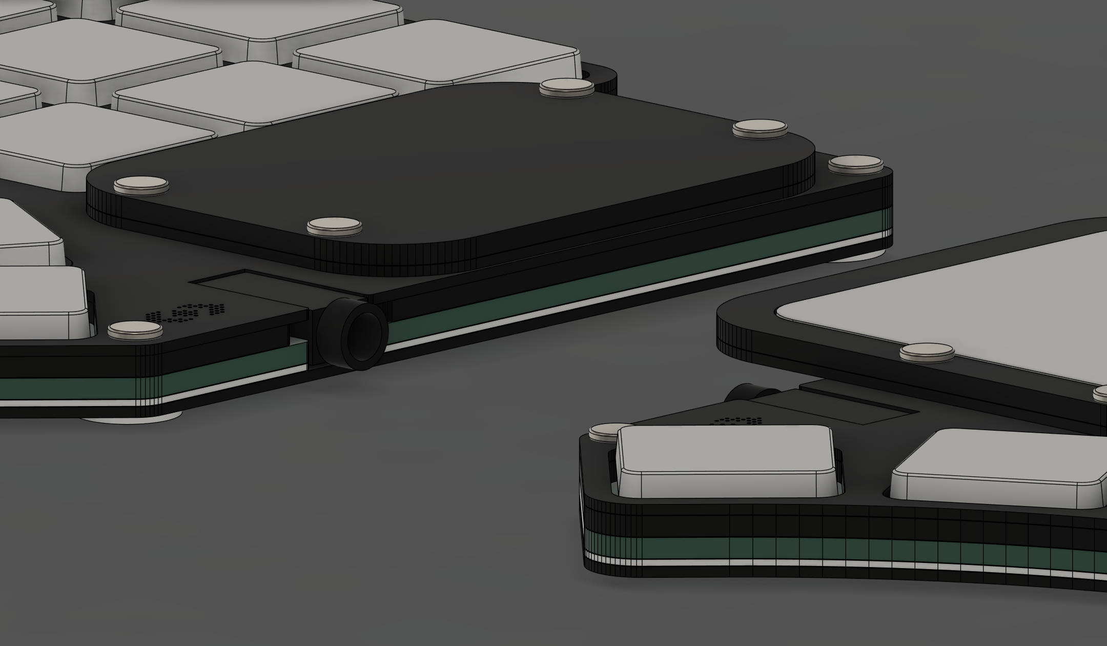 |
|---|
| 順序 | 部件 | 厚度(mm) | 備註 |
|---|---|---|---|
| 1 | 上蓋-A(Cover-A)、觸控板邊框-A(Track-A) | 1.6 | 有無觸控板做選擇 |
| 2 | 上蓋-B(Cover-B)、觸控板邊框-B(Track-B) | 0.8 | 有無觸控板做選擇 |
| 3 | 定位板(Plate) | 0.8 | - |
| 4 | 間隙空間板(Body) | 1.6 | - |
| 5 | 核心電路板(Main) | 1.6 | - |
| 6 | 緩衝層(Frame) | 0.5-0.8 | 自行裁切或使用電路板層都可 |
| 7 | 底板(Bottom) | 0.8 | - |
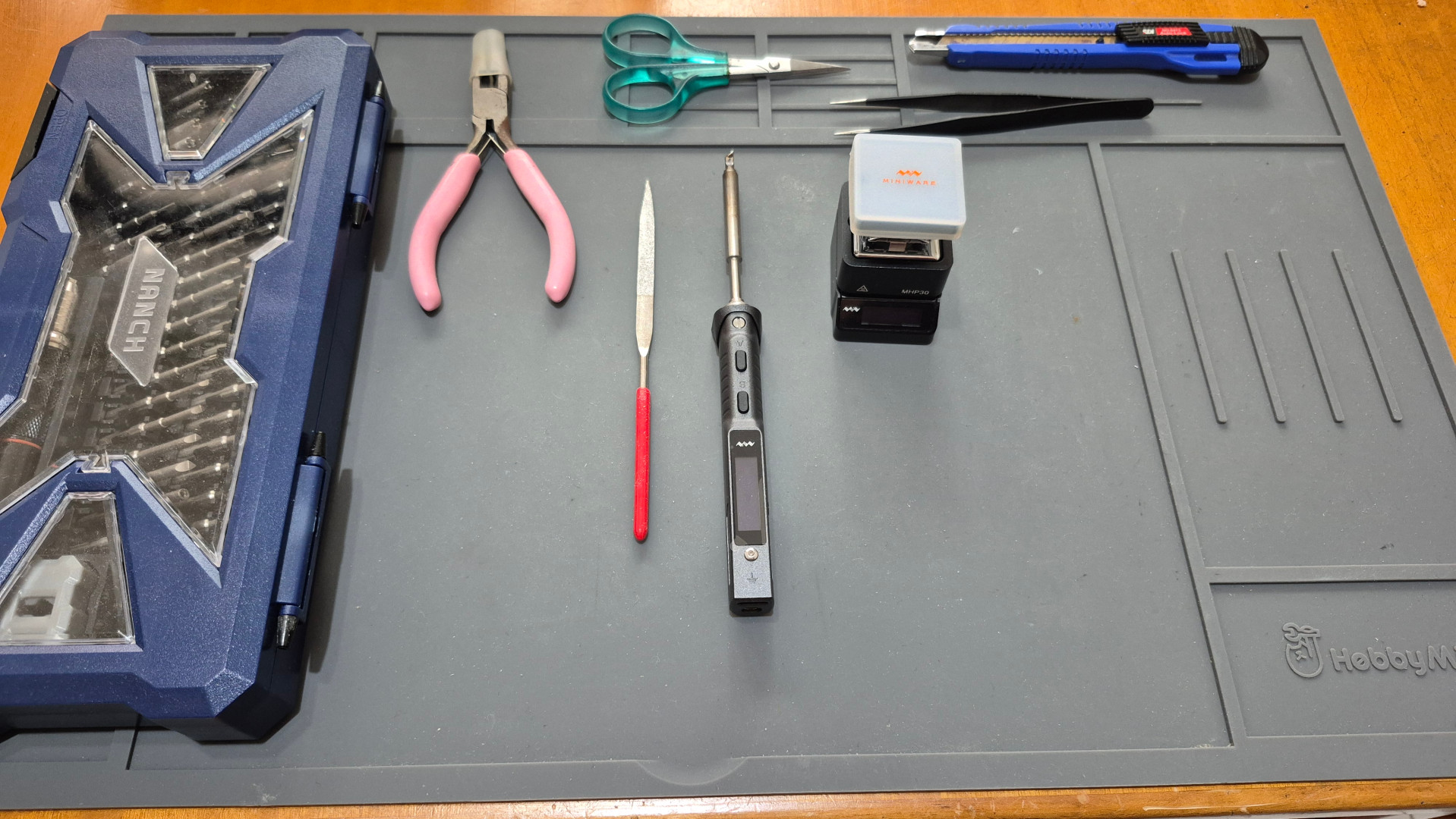
| 名稱 | 使用場合 | 備註 | |
|---|---|---|---|
| 1 | 電烙鐵 | 基本電路板焊接 | 修正焊錫使用,推薦使用K頭(刀頭) |
| 2 | 熱風槍或加熱台 | 進階電路板焊接 | 擇一使用即可 |
| 3 | 針筒裝錫膏 | 進階電路板焊接 | |
| 4 | 剪刀及美工刀 | 裁切膠帶及塑料板材 | |
| 5 | 超薄超黏雙面膠 | 粘貼固定觸控板用 | 0.13-0.15mm厚度的即可 |
| 6 | 對應電路板顏色的簽字筆 | 邊框填色使用 | 可不需使用 |
| 7 | 防靜電金屬鑷子 | 進階電路板焊接、測試、精密操作 | |
| 8 | 精密螺絲起子 | - | 對應螺絲規格使用 |
| 9 | 平口老虎鉗 | 分離拼接電路板時使用 | |
| 10 | 銼刀 | 打磨電路板邊框時用 | |
| 11 | 皮革打洞器 | 裁切矽膠墊使用 | 需要打ø4-4.5mm的孔 |
| 12 | 鉛筆或原子筆 | 裁切PVC塑膠板時使用 | |
| 13 | 3秒膠或AB膠 | 固定層板使用 |
| 圖示 | 說明 |
|---|---|
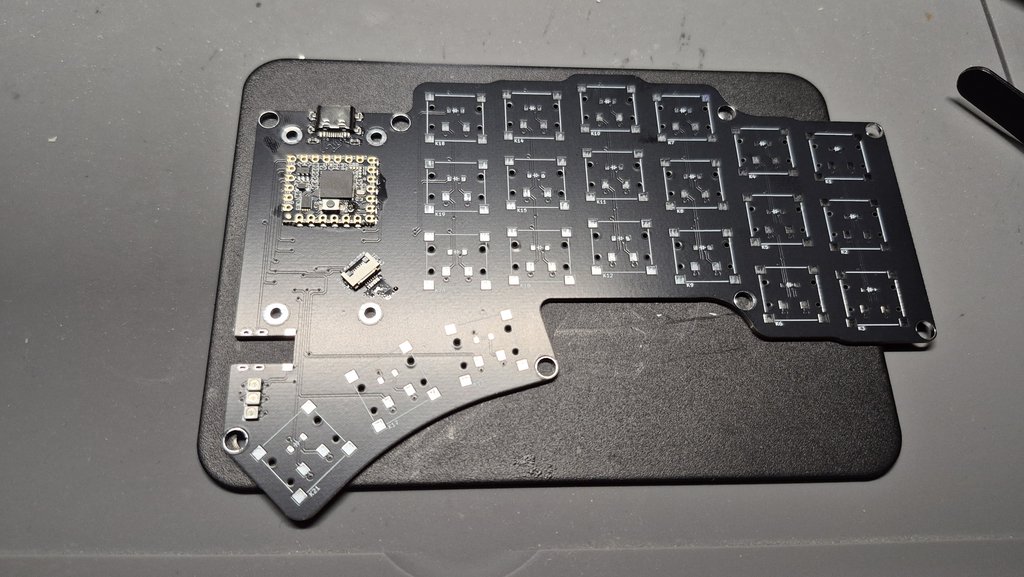 | 首先將MCU、USB-C接口、5.1K電阻及FFC排線座焊接好。 |
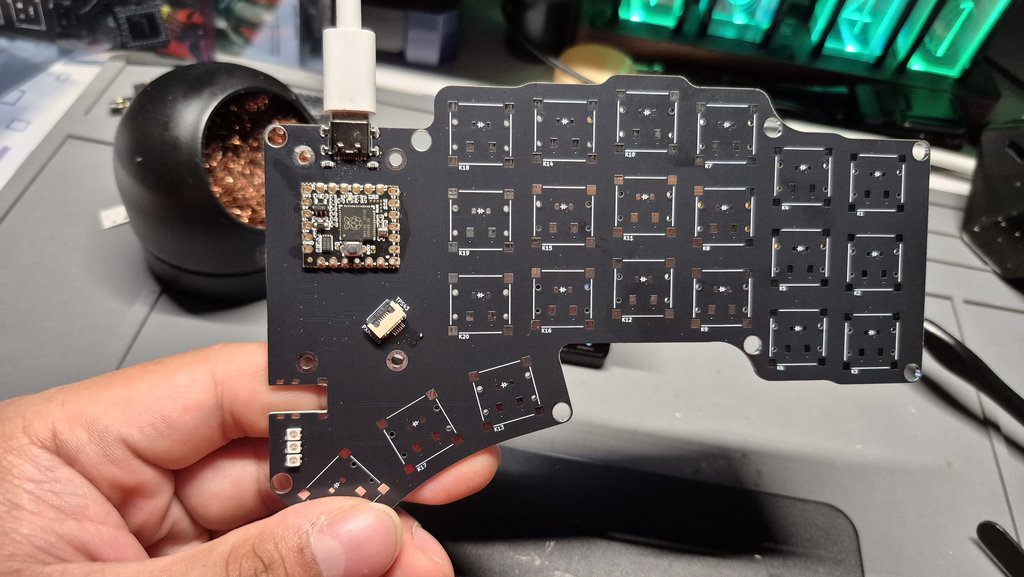 | 連接電腦測試MCU的狀態,如果順利接通MCU的話,MCU上面的橘紅色LED燈會閃爍。 |
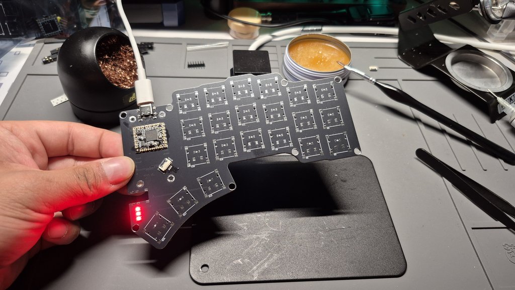 | 請根據RP2040的燒錄方式將韌體燒錄至MCU,成功的話LED燈會亮,還有VIAL會成功讀取到鍵盤。 |
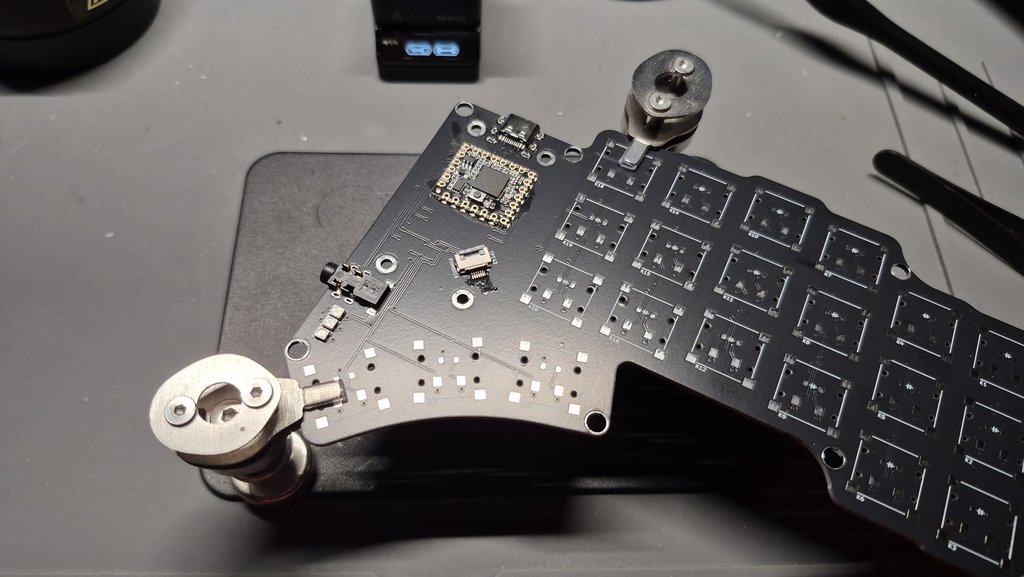 | 再來焊接TRRS座。 |
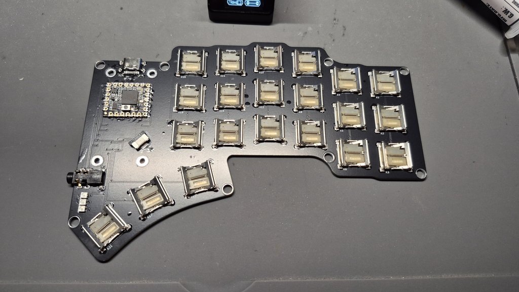 | 接著按照順序將1N4148及PG1316S焊接起來,PG1316S的燈光孔是可以容下1N4148的,務必將二極體包覆在軸燈燈孔裡面。 |
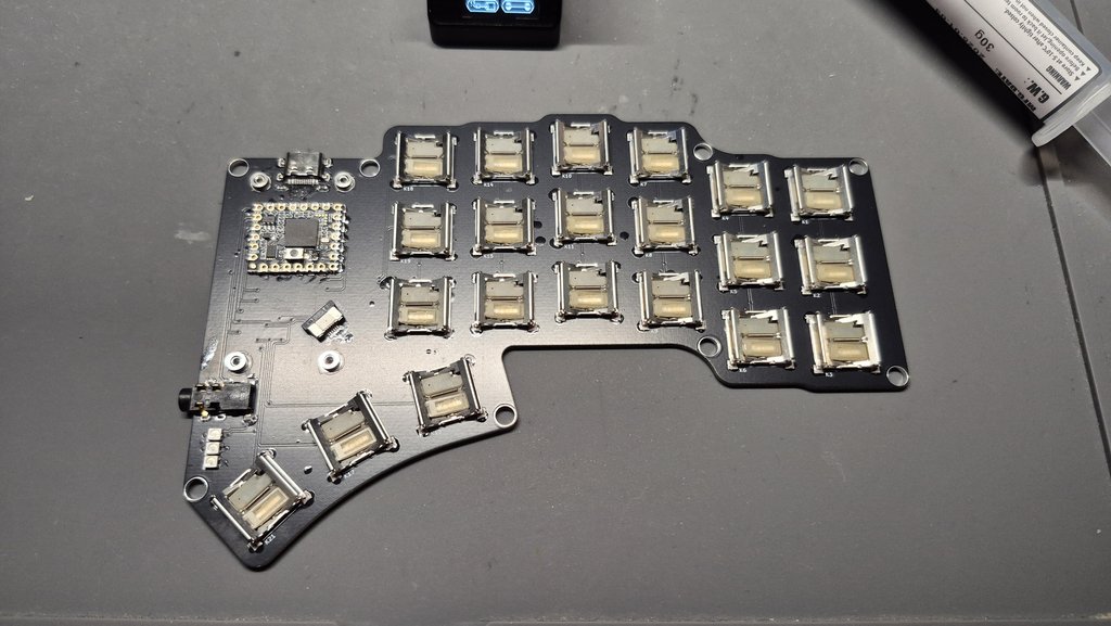 | 然後將貼片銅柱(MAC8 TH1.6-2.0-M2)焊接上去。 |
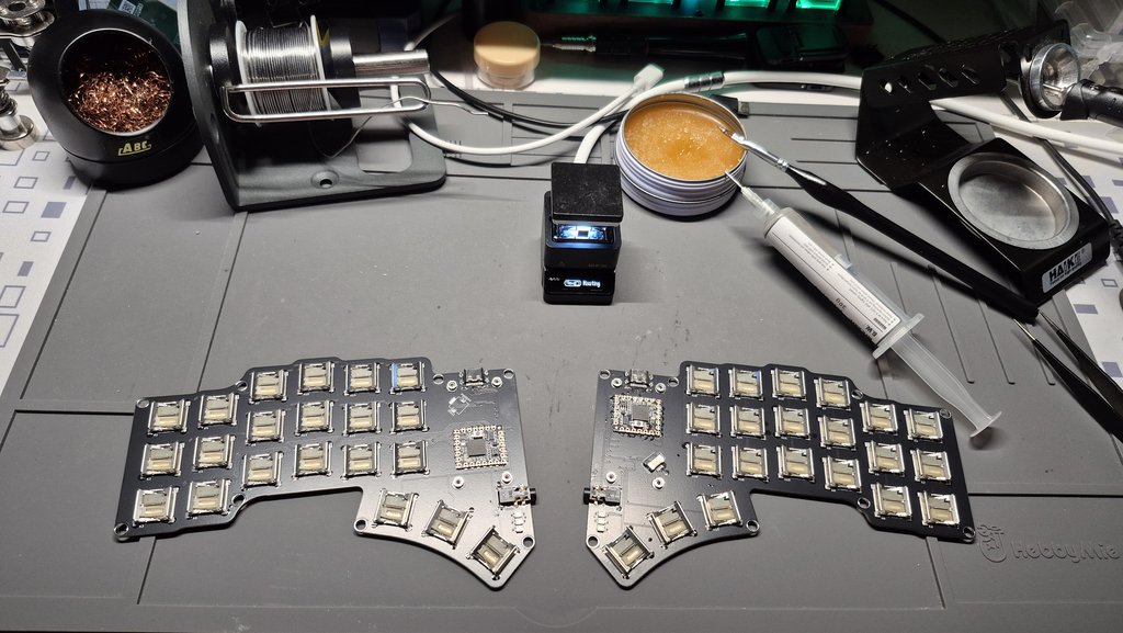 | 接著將另一側鍵盤也焊好。 |
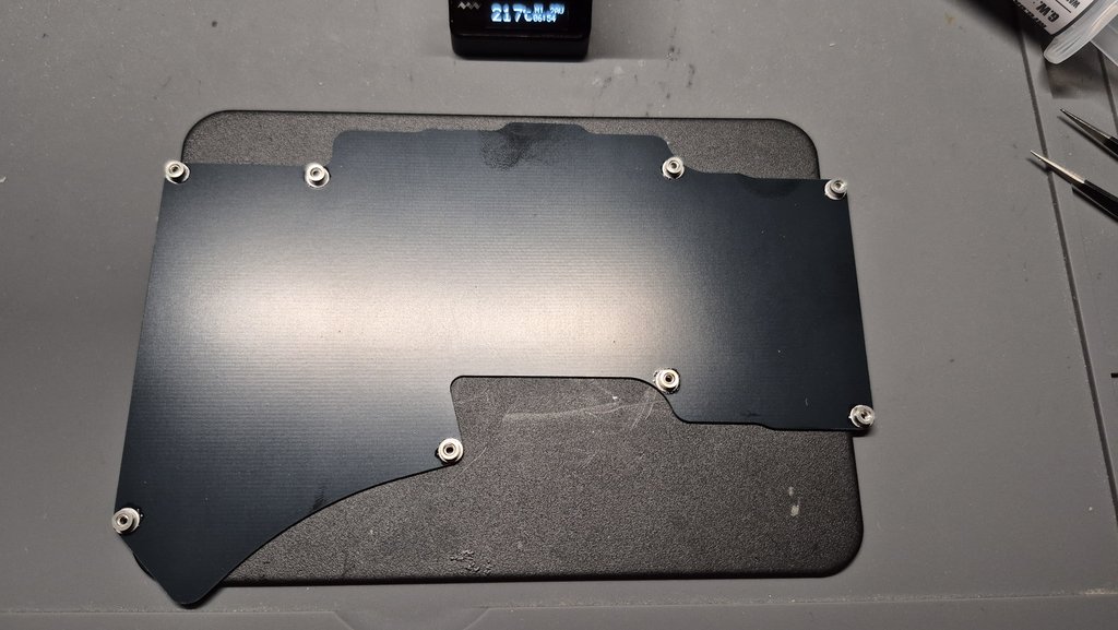 | 再來將底板(Bottom)的貼片銅柱(MAC8 TH0.8-2.0-M2)也焊接固定好。 |
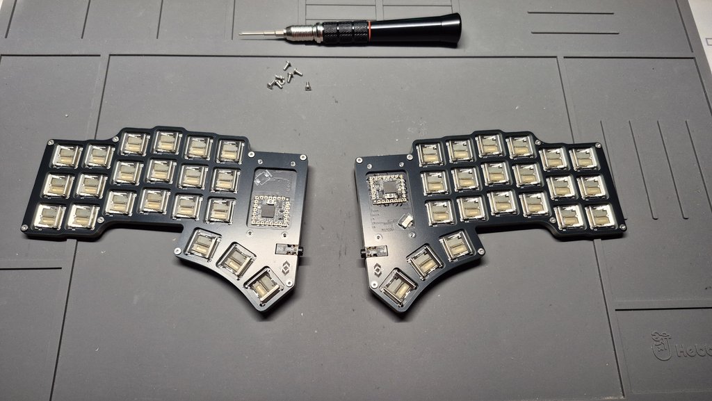 | 接著依照底板(Bottom)、緩衝層(Frame)、電路板(Main)、間隙(Body)、定位板(Plate)的順序將鍵盤疊好,再把鍵盤外側的螺絲鎖上去固定。 |
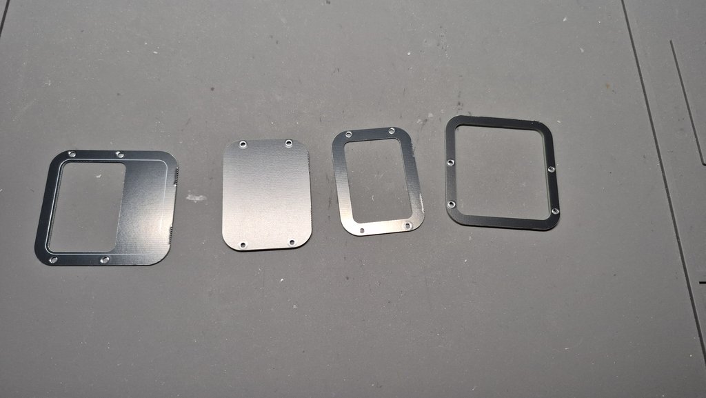 | 將Cover-A、Cover-B、Track-A、Track-B用工具剝下來。 |
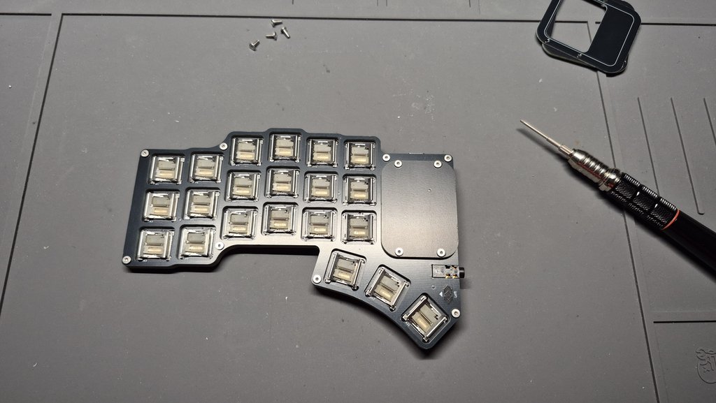 | 然後將其中一側的Cover蓋起來用螺絲鎖好,完成其中一邊,如果不需要安裝觸控板就把兩側鍵盤都鎖上Cover就完成了。 |
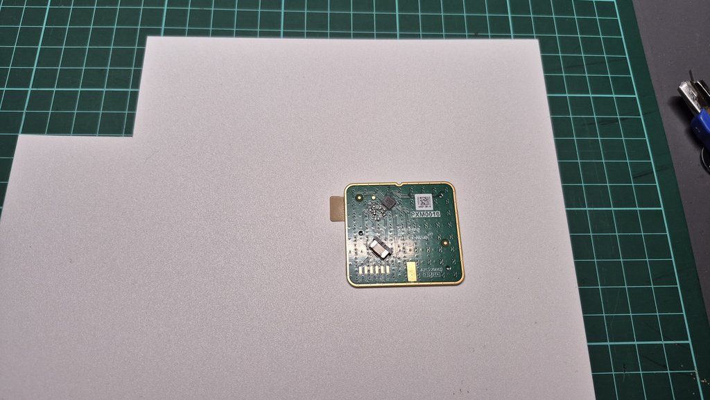 | 觸控板的部分可以選擇使用列印或自己切觸控板Cover。 |
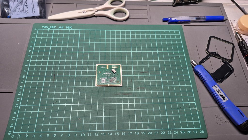 | 首先將觸控板上的3M貼紙撕下來貼在8mm的PVC板材上後裁切下來,再把多餘的邊切除。 |
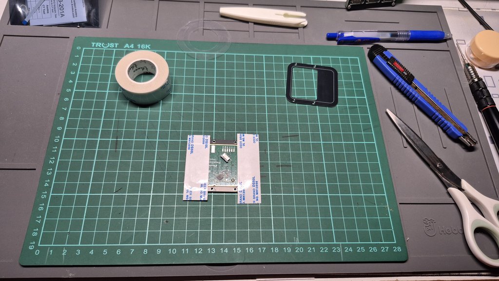 | 好了之後將Track-A固定好,貼上超黏雙面膠。 |
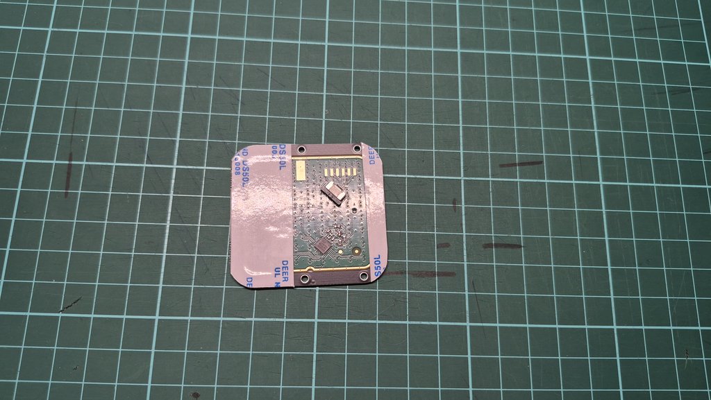 | 一樣切除多餘的膠。 |
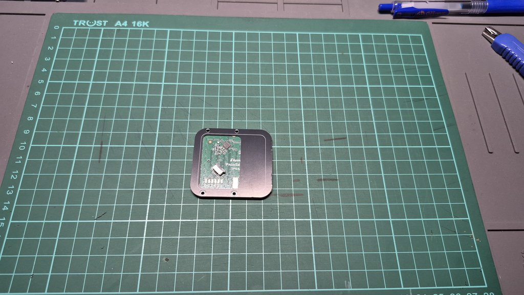 | 撕下膠的另一面之後,將A、B合併在一起。 |
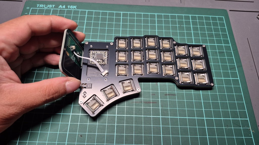 | 接上排線,稍微彎折收納一下排線。 |
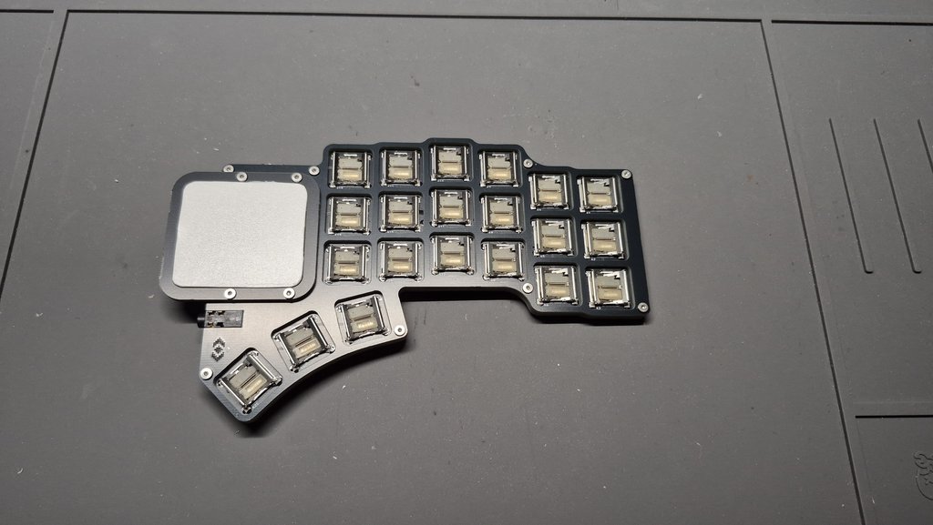 | 鎖上螺絲。 |
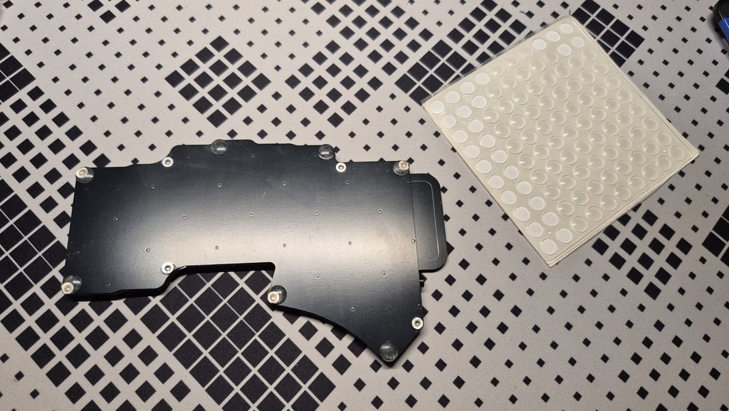 | 然後翻到背面貼上腳貼或自行DIY上Tending。 |
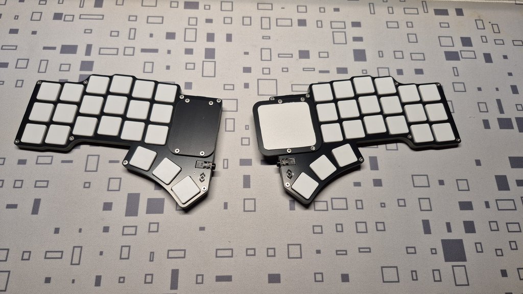 | 安裝鍵帽之後就完成啦。 |
| Qty | Value | Footprint | References |
|---|---|---|---|
| 21 | 1N4148_SMD | DreaM117er-keebLibrary:D_SOD-123_dual | D1, D2, D3, D4, D10, D11, D12, D13, D14, D15, D16, D17, D18, D19, D20, D21 +5 |
| 21 | PG1316S | DreaM117er-keebLibrary:SW_Kailh_PG1316S_1.00u_Dual2 | K1, K2, K3, K4, K10, K11, K12, K13, K14, K15, K16, K17, K18, K19, K20, K21 +5 |
| 8 | 4.2mm | DreaM117er-keebLibrary:MAC8_TH0816-XX-M2-NPTHhole | N1, N2, N3, N4, N5, N6, N7, N8 |
| 6 | SK6805 | DreaM117er-keebLibrary:LED_SK6805_PLCC4_2.4x2.7mm_P1.3mm | L1, L2, L3, L4, L5, L6 |
| 4 | 5.1K | Resistor_SMD:R_0603_1608Metric | R1, R2, R3, R4 |
| 4 | MAC8 TH1.6-0.3 M2 | DreaM117er-keebLibrary:MAC8_TH0816-XX-M2-Dual_Pad | N9, N10, N11, N12 |
| 2 | MCU_RP2040_CoreA_SMD | DreaM117er-keebLibrary:MCU_RP2040CoreA_SMD | U1, U2 |
| 2 | TPS43-201A-S | DreaM117er-keebLibrary:Hirose_FH12-6S-0.5SH_1x06-1MP_P0.50mm_Horizontal | J2, J3 |
| 2 | USB_C_Plug_USB2.0 | DreaM117er-keebLibrary:USB_C_16P_MID_MOUT_SR_Molex | P1, P2 |
| 1 | AudioJack3 | DreaM117er-keebLibrary:TRRS-PJ-381-BB_6P_Dual | J1 |
| 1 | TPS43-201A-S | DreaM117er-keebLibrary:Azoteq_TPS43_201A_S | TRK1 |
The 72 most common of 74 parts.
DreaM117er/Paicorea
Paicorea is a 42 keys split keyboard, with optional way to drive Azoteq TPS43 trackpad.

mornepousse/SpLiT_KaSe
Custom ergonomic split fully-wireless keyboard - ESP32-S3, NRF24L01+, KiCad 9


fellettigiacomo/NeoHeart
Open Source ATtiny816-based heart shaped PCB with Addressable LEDs!


pierrebaillargeon/Microplate-Assistive-Pipetting-Light-Emitter
Microplate Assistive Pipetting Light Emitter (M.A.P.L.E.)
It measures 155.9 × 107.2 mm and has 2 copper layers, 1.6 mm thick.
74 parts, built around the TPS43-201A-S and SK6805E-J. The full list of its parts is on this page, with links to each part's symbol and footprint where PCBKit's library has them.
From the DreaM117er/Paicorea repository on GitHub, at the commit this page was made from: the board is file/pcb/main/main.kicad_pcb and its schematic file/pcb/body/body.kicad_sch. PCBKit opens the board in the browser, with nothing to install.
Its repository publishes it under the MIT licence: you may reuse it on that licence's terms (keep the author's notice, and for a copyleft licence share your changes alike).