Ttt ttl is an open-source printed circuit board by DoctorWkt, from the DoctorWkt/TTL_TicTacToe repository on GitHub, published under the GPL-3.0 licence. It is a 2-layer board of 79.8 × 129.5 mm with 82 parts on 106 nets, routed with 1,186 tracks and 5 vias.
It is built around the 74LS109PC, 74LS161DC and NE555. Its parts include 33 resistors, 20 diodes, 13 ICs, 11 switches and 3 capacitors.
I've seen several circuits for two-player tic-tac-toe games on the Internet,
but I thought I'd try to design one with these constraints:
done with TTL components only, no CPU
minimum number of chips
not two player: human versus the board, board makes optimal moves
This is the repository for my result. The circuit uses flip-flops to
register both the human and the board's moves. The board has a register
which holds the current state of the board's moves. The board state and
the user's moves are combined to access a ROM to look up the next board move
and any tie or win result.
An overview of the design is available. Here's
a video of the board in action.
There are several versions of the design.
Logisim Version
I built this Logisim version in preparation for
designing the real circuit with TTL components. If you haven't used
Logisim before, open up the *.circ
file. Now start the clock with a control-K (or use
Simulate -> Ticks Enabled). Now that the circuit is running, click on
the brown finger icon (the poke tool) at the top-left so that you can
press the game buttons.
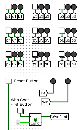
Over on the right you will see a 3x3 grid. The white squares are the
pushbuttons to make a move. Next to each button is a red LED to register
the user's move and a blue LED for the board's moves.
Below this grid there is a Reset button and a "Who Goes First" button.
Press the "Who Goes First" button to toggle between the user moving
first and the board moving first. Then press the Reset button to clear
the board.
Now press the user moves buttons to make your moves. Immediately after
each move, the board will make a move. When a tie occurs, the Tie LED
will light up. When the board wins, the Win LED will light up.
Over on the left are the nine JK flip-flops to record the user's moves,
and the nine JK flip-flops to record the board's moves. Below that is
the ROM which generates a 4-bit value which is the new board's move.
The 4-bit board move goes into the 4:16 demultiplexer to generate the nine
lines which go to the nine JK flip-flops to record the board's moves.
Two of the 16 possible moves are used to indicate a tie or a board win.
The ROM also generates the next state of the board's moves. This is
recorded into a 4-bit register. See the design notes
for details of the state number.
The circuit should come with the latest version of the ROM image. If you
ever regenerate the ttt.rom file, here is how to load it into the circuit.
Right-click on the ROM device in the circuit and choose Load image and
choose the ttl.rom file to load.
Kicad Schematic
In the Schematic/ folder you will find a
Kicad schematic for the circuit. This uses:
nine 74HC107 dual JK flip flops. Each one holds both the user and board
move for one position on the board
one 28C256 32Kx8 EEPROM to look up the next board move. We only use
8K of the space in the EEPROM.
one 74HC154 4:16 demultiplexer
one 75HC161 register to hold the board state number
one 555 to generate the clock signal
various LEDs to show the moves, and other sundry components.
I've also designed a PCB to hold all the components.
The design has separate LEDs for user and board moves, but I've chosen to use
bi-colour LEDs so that there is a single physical LED for each board position:
green for the user, red for the board, off when empty.
Generating the 28C256 EEPROM Contents
At the Linux command-line, run the command:
text
make
This will use the gen_moves.pl script to generate the user-first moves file
umoves, and the board-first moves file bmoves. These are then parsed by
the parse_moves.pl script to create the ttt.rom file used by Logisim.
Finally, the hex2bin script takes the ttt.rom file, which is hex-encoded,
and converts it to the binary file 28C256.bin which can be burned to the
EEPROM.
If you have a MiniPro EEPROM burner and the minipro command installed,
text
make write
will burn the 28C256.bin to a 28C256 chip with the MiniPro burner.
This is just a simple backup of all the files related to the Centurion that I have stored on my HD. The Wiki itself has far more in-depth information about the Centurion and it's individual cards.
It measures 79.8 × 129.5 mm and has 2 copper layers, 1.6 mm thick.
What parts does the Ttt ttl use?
82 parts, built around the 74LS109PC, 74LS161DC and NE555. The full list of its parts is on this page, with links to each part's symbol and footprint where PCBKit's library has them.
Where can I download the Ttt ttl KiCad files?
From the DoctorWkt/TTL_TicTacToe repository on GitHub, at the commit this page was made from: the board is Schematic/ttt_ttl.kicad_pcb. PCBKit opens the board in the browser, with nothing to install.
Can I use the Ttt ttl design in my own project?
Its repository publishes it under the GPL-3.0 licence: you may reuse it on that licence's terms (keep the author's notice, and for a copyleft licence share your changes alike).