
2 layers132.1 × 45.7 mm
IPoS
peterheinrich/InternetOverSpaghetti
Transmitting IP packages over a pair of spaghetti thus demonstrating how media independent IP really is.
42 parts342

 DishanPanchigar/Analog_PID_Controller
An all-hardware Proportional-Integral-Derivative (PID) controller built entirely from op-amps, resistors, and capacitors — no microcontroller, no code.
Analog PID Controller is an open-source printed circuit board by DishanPanchigar, from the DishanPanchigar/Analog_PID_Controller repository on GitHub. It is a 2-layer board of 81.8 × 78 mm with 45 parts on 23 nets, routed with 224 tracks and 45 vias.
It is built around the LM358. Its parts include 18 resistors, 10 capacitors, 4 ICs and 4 connectors.
An all-hardware Proportional-Integral-Derivative (PID) controller built entirely from op-amps, resistors, and capacitors — no microcontroller, no code. Designed and simulated in Proteus, hand-built on a proto-board, and laid out as a two-layer PCB in KiCad.
Analog Circuit Course (BECE206L) project — School of Electronics Engineering, VIT Chennai.
Digital PID controllers dominate modern practice, but analog controllers still have a place where continuous-time response, zero sampling delay, and simplicity matter. This project implements the classic PID control law directly in hardware using LM358 op-amps:
The design was validated at three levels: theoretical modeling, Proteus simulation, and hardware prototyping — followed by a proper two-layer PCB layout in KiCad.
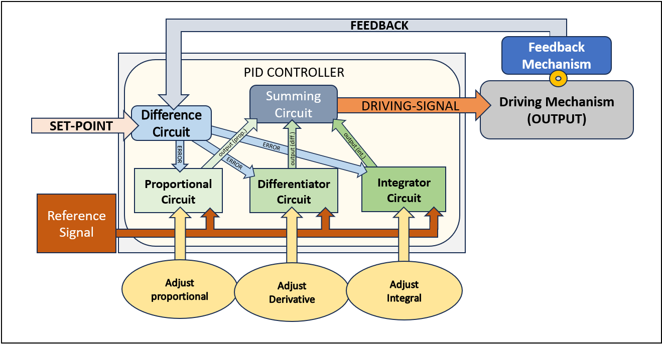
The input error signal is fed in parallel to the proportional, integral, and derivative stages. Each stage produces its own control voltage, and a summing amplifier combines them into the final output, exactly as in the classical PID equation.
Vout = Kp·Vin + Ki∫Vin dt + Kd·dVin/dt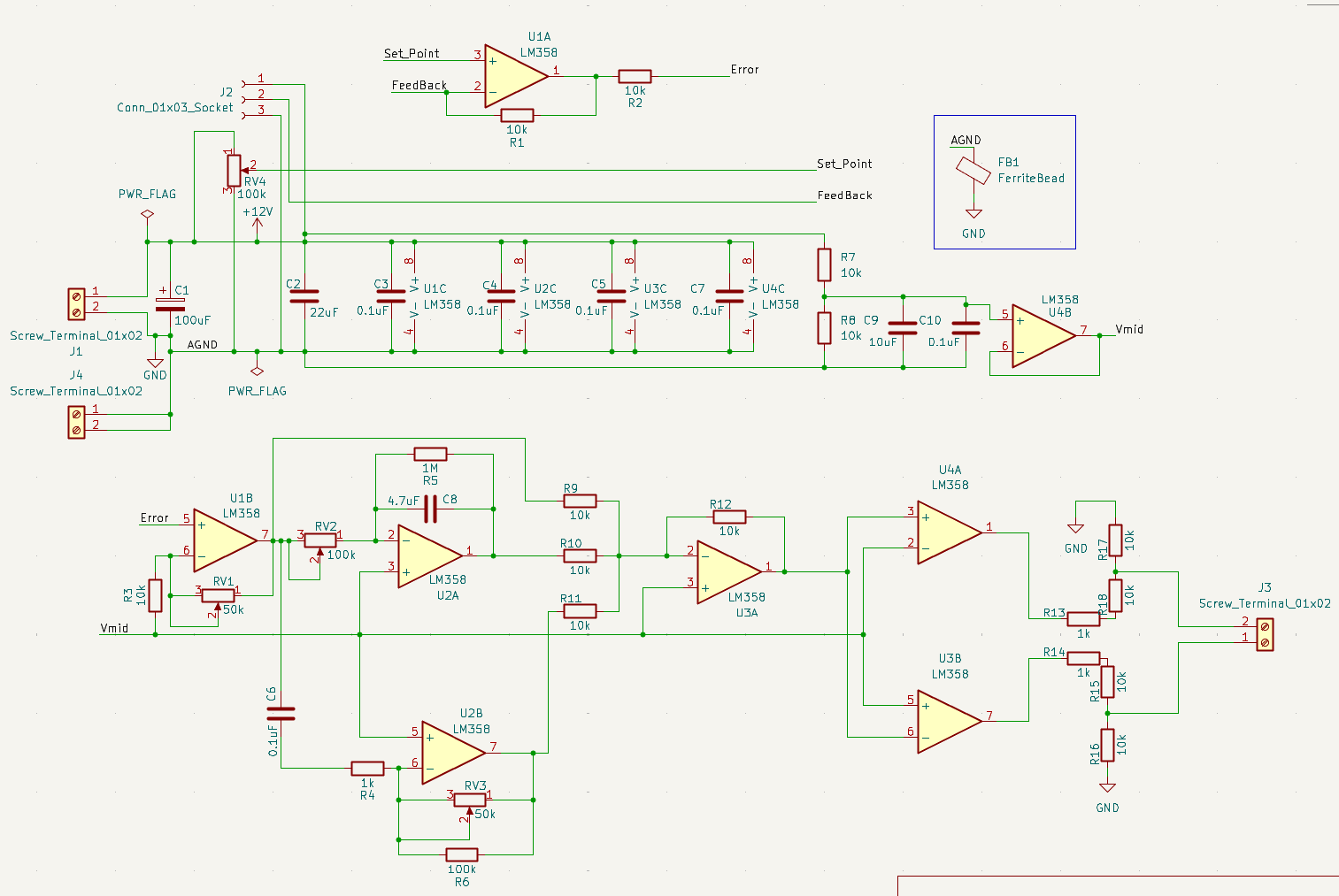
Proportional stage — inverting amp, gain set by potentiometer RV1:
Vprop = -(RV1 / R2) · Vin = -Kp · VinIntegral stage — op-amp integrator, R = RV2, C1 = 4.7 µF (with a parallel resistor to prevent saturation drift):
Vint = -(1 / RV2·C1) ∫ Vin dt = -Ki ∫ Vin dtDerivative stage — practical differentiator, C2 = 0.1 µF, R = R5 ∥ RV3 (extra resistors limit high-frequency noise gain):
Vdiff = -(Req·C2) · dVin/dt = -Kd · dVin/dtSumming amplifier — inverting summer that combines all three stages:
Vout = Kp·Vin + Ki∫Vin dt + Kd·dVin/dt| Component | Choice | Why |
|---|---|---|
| Op-amp | LM358 | Cheap, single-supply (3–32 V), low offset (~2 mV), 1 MHz GBW, low bias current — good enough for low-frequency PID work |
| Resistors | 1 kΩ – 1 MΩ | Gain/stability setting per stage |
| Capacitors | 0.1 µF – 4.7 µF | Integration / differentiation |
| Filter caps | 10 µF – 100 µF | Power-rail smoothing |
| Potentiometers | RV1–RV4 | Live tuning of Kp, Ki, Kd, and set-point |
Power supply & virtual ground: a +12 V single-rail supply is split by two 10 kΩ resistors into a 6 V midpoint, buffered by an LM358 voltage-follower to hold a stable virtual ground under load — this is what lets every op-amp stage handle bipolar signals from a single supply.
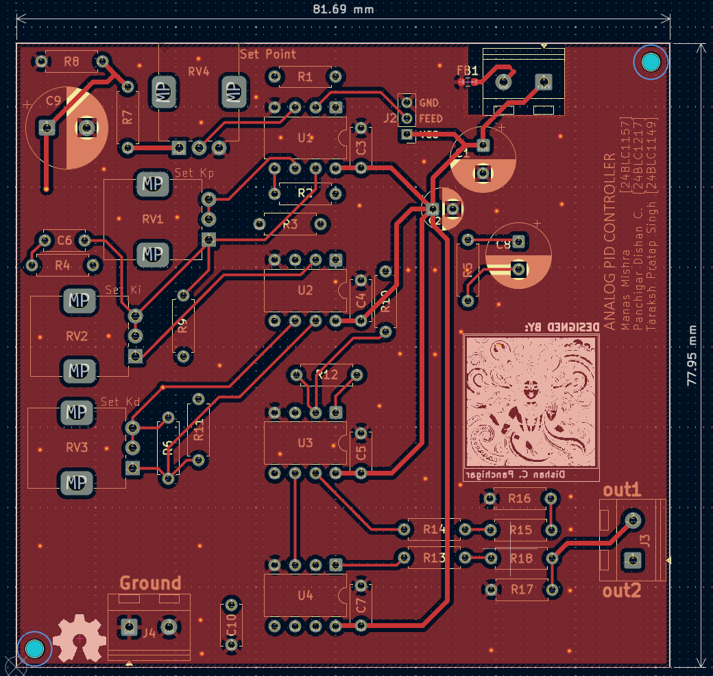
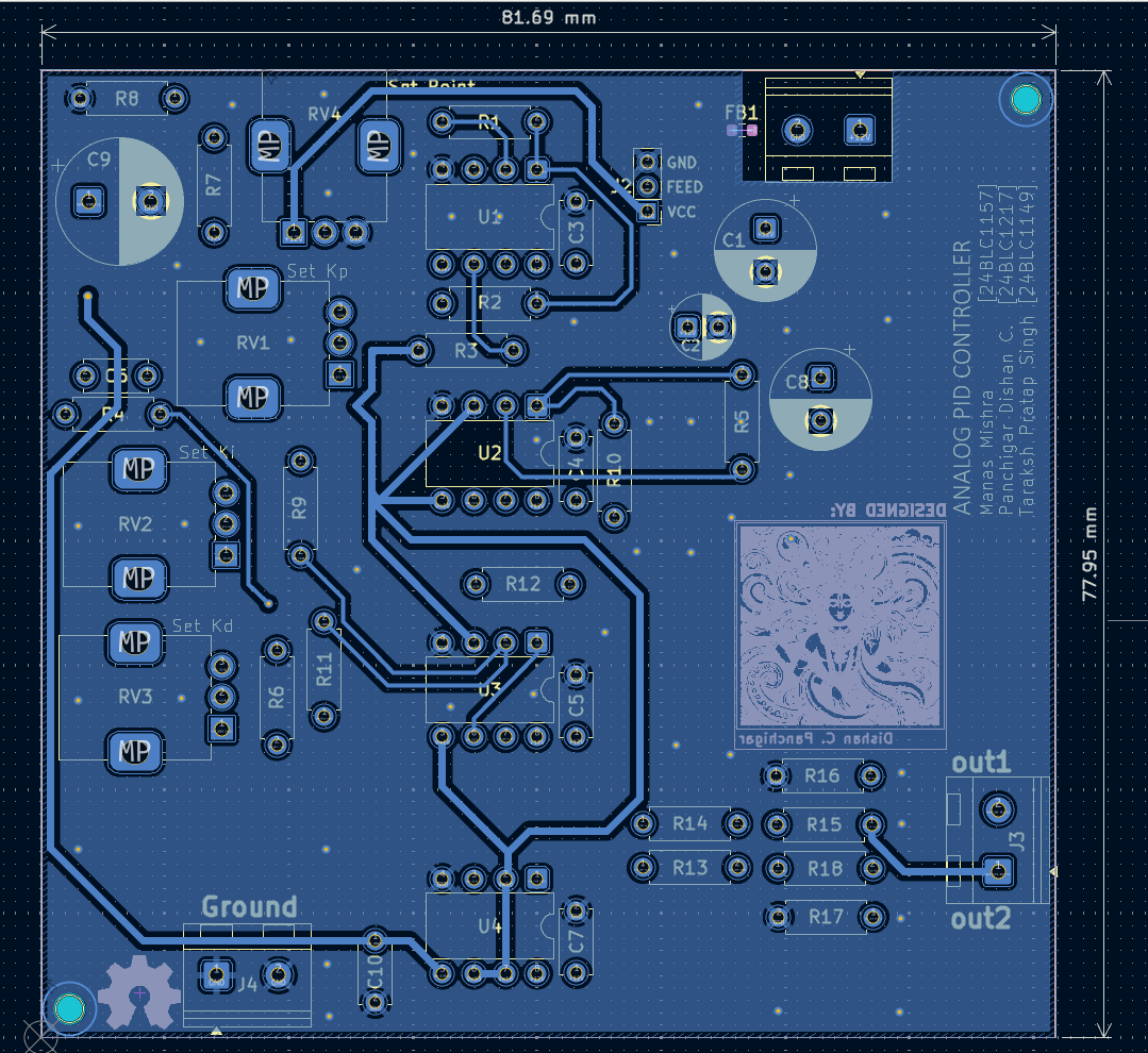
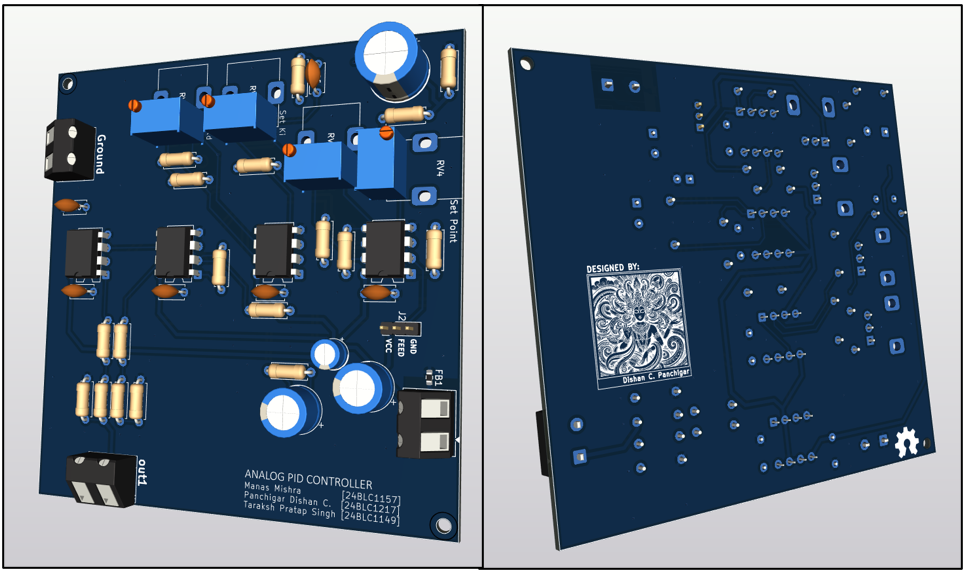
Two-layer board designed in KiCad. Front layer carries the active components (U1–U4 op-amps, R1–R18, C1–C10, tuning pots RV1–RV4); back layer is largely ground plane and power routing, stitched together with vias to keep the analog signal paths low-noise.
| Front layer | Back layer |
|---|---|
 |  |
3D render of the finished board:
Noise reduction techniques used:
Gerbers and native KiCad project files are included in PCB Design/.
Each stage (P, I, D) was verified independently before being combined through the summing amplifier.

Set-point and feedback potentiometers were swept to observe the controller's response under different gain conditions:
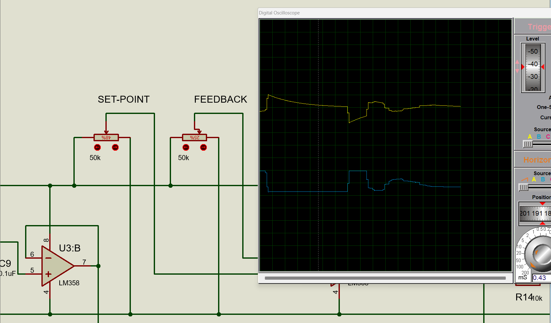
The yellow trace shows the instantaneous error signal; the blue trace shows the controller's driving output as it reacts to that error. Sweeping Kp, Ki, and Kd this way surfaced two real issues that were fixed before moving to hardware: excessive high-frequency noise gain in the derivative stage (fixed by re-tuning the differentiator capacitor for a mild low-pass effect) and op-amp saturation from mismatched resistor ratios.
The power supply and virtual ground were built and verified first, then each PID stage was built and tested individually before being tied together with the summing amplifier.
| Front | Back |
|---|---|
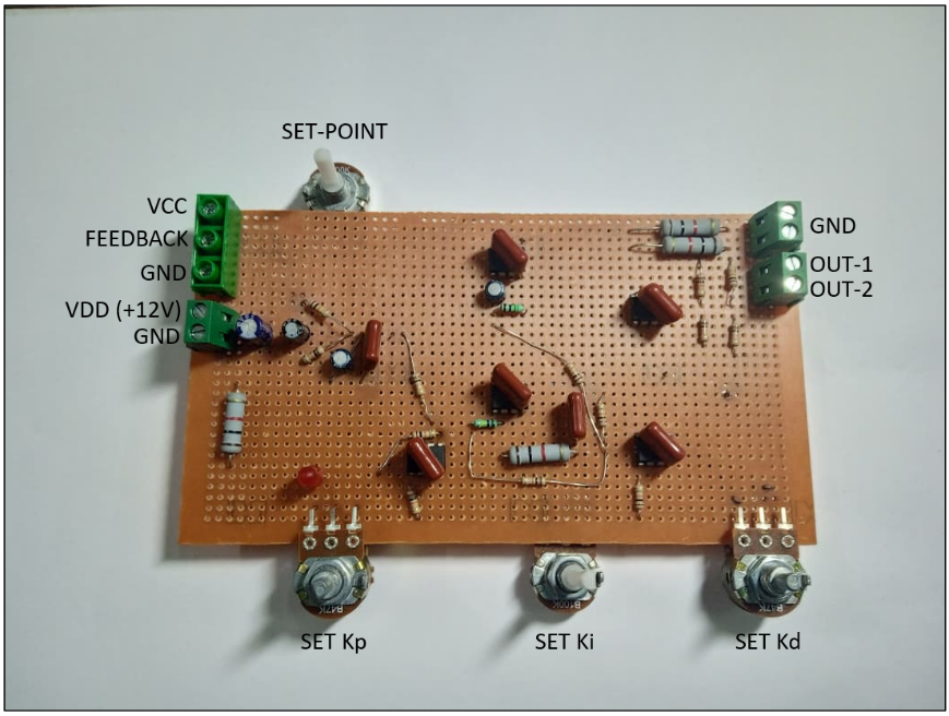 | 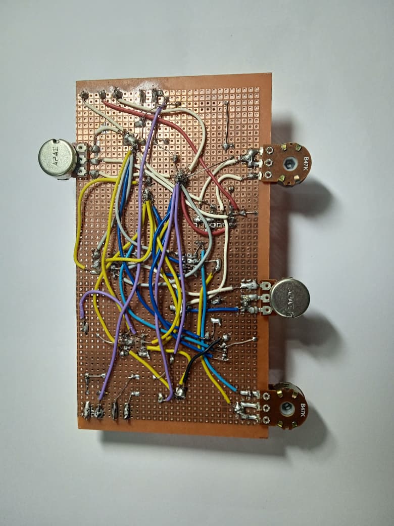 |
Assembled and running:
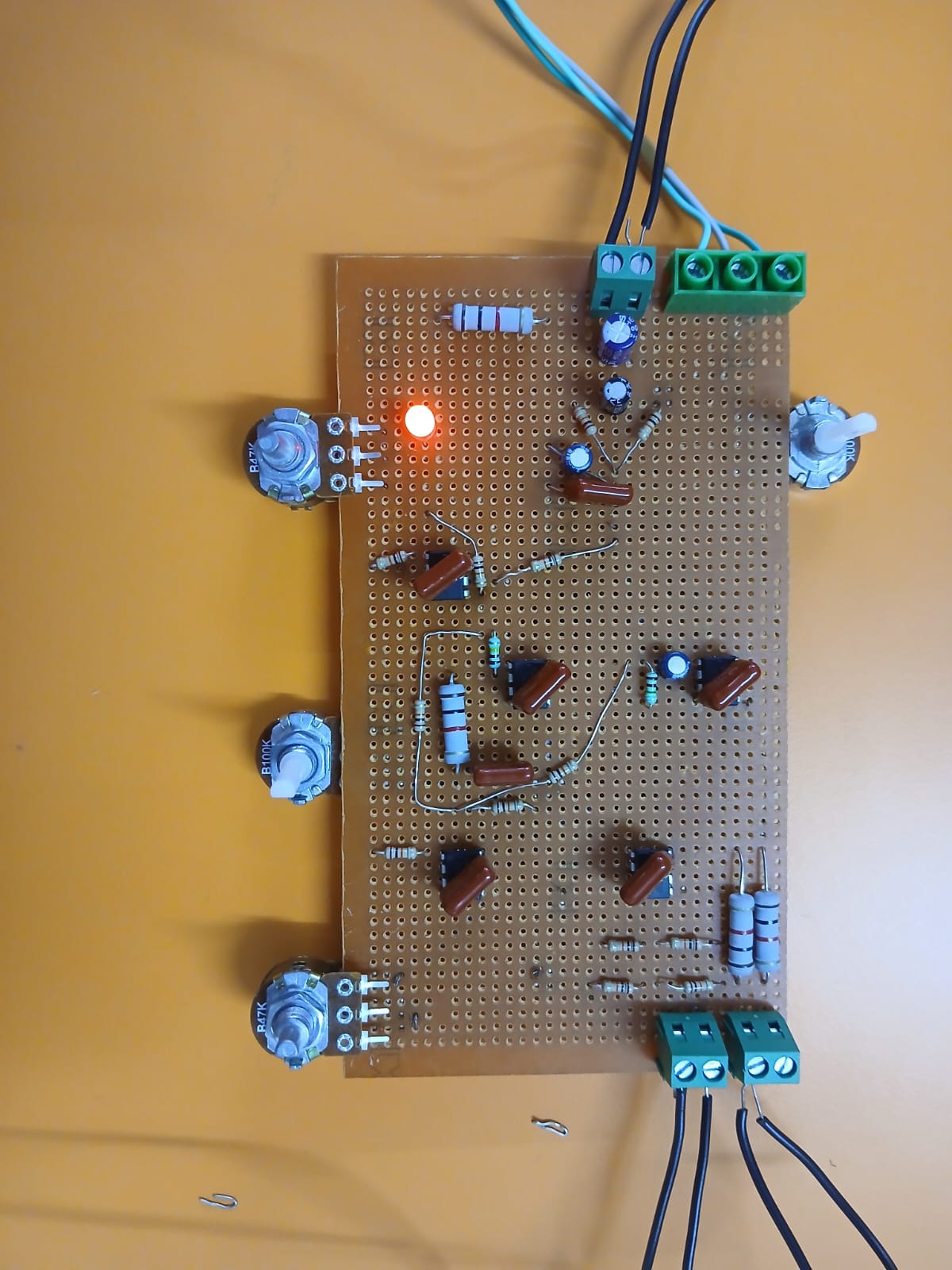
The board was powered from a regulated +12 V supply, with an oscilloscope and multimeter monitoring the outputs while the set-point/feedback potentiometers and the Kp/Ki/Kd trim pots were adjusted.
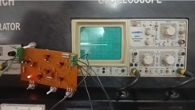
Overall, the controller reduced steady-state error, improved rise time, and stayed stable across the tested range of Kp/Ki/Kd settings — confirming that a fully analog, code-free PID implementation is viable for real-time, low-latency control.
.
├── Analog Circuit_Project_Report.docx   # Full project report
├── PCB Design/
│   ├── Analog_PID_Controller.kicad_pro
│   ├── Analog_PID_Controller.kicad_sch  # Schematic
│   ├── Analog_PID_Controller.kicad_pcb  # PCB layout
│   └── Gerbers/                         # Fabrication files (Gerbers + drill files)
└── images/ # Figures used in this READMEPCB Design/)Course project under Dr. Raju Patel, School of Electronics Engineering, VIT Chennai — April 2026.
See the full report for the complete bibliography, including foundational PID texts (Åström & Hägglund, Ogata, Visioli) and recent literature on analog vs. digital and adaptive PID implementations.
| Qty | Value | Footprint | References |
|---|---|---|---|
| 13 | 10k | Resistor_THT:R_Axial_DIN0207_L6.3mm_D2.5mm_P7.62mm_Horizontal | R1, R2, R3, R7, R8, R9, R10, R11, R12, R15, R16, R17, R18 |
| 6 | 0.1uF | Capacitor_THT:C_Disc_D5.0mm_W2.5mm_P5.00mm | C3, C4, C5, C6, C7, C10 |
| 4 | LM358 | Package_DIP:DIP-8_W7.62mm | U1, U2, U3, U4 |
| 3 | 1k | Resistor_THT:R_Axial_DIN0207_L6.3mm_D2.5mm_P7.62mm_Horizontal | R4, R13, R14 |
| 3 | Screw_Terminal_01x02 | TerminalBlock_RND:TerminalBlock_RND_205-00045_1x02_P5.00mm_Horizontal | J1, J3, J4 |
| 2 | 100k | Potentiometer_THT:Potentiometer_Alps_RK09K_Single_Vertical | RV2, RV4 |
| 2 | 50k | Potentiometer_THT:Potentiometer_Alps_RK09K_Single_Vertical | RV1, RV3 |
| 1 | 100k | Resistor_THT:R_Axial_DIN0207_L6.3mm_D2.5mm_P7.62mm_Horizontal | R6 |
| 1 | 100uF | Capacitor_THT:CP_Radial_D8.0mm_P3.50mm | C1 |
| 1 | 10uF | Capacitor_THT:CP_Radial_D10.0mm_P5.00mm | C9 |
| 1 | 1M | Resistor_THT:R_Axial_DIN0207_L6.3mm_D2.5mm_P7.62mm_Horizontal | R5 |
| 1 | 22uF | Capacitor_THT:CP_Radial_D5.0mm_P2.50mm | C2 |
| 1 | 4.7uF | Capacitor_THT:CP_Radial_D8.0mm_P3.50mm | C8 |
| 1 | Conn_01x03_Socket | Connector_PinHeader_2.00mm:PinHeader_1x03_P2.00mm_Vertical | J2 |
| 1 | FerriteBead | Resistor_SMD:R_0603_1608Metric | FB1 |
| 1 | LOGO | LOGO | G*** |
The 42 most common of 45 parts.
peterheinrich/InternetOverSpaghetti
Transmitting IP packages over a pair of spaghetti thus demonstrating how media independent IP really is.

zmaker/arduino_cookbook
gli sketch del nuovo progetto Arduino Cookbook e dei video di YouTube

profdc9/RFBitBanger
A QRP digital transceiver created from readily available parts for off-the-grid maintenance


tvlad1234/pillScopePlus
Oscilloscope based around the STM32F401 Black Pill and a color LCD screen


starlightk7/OpenSFC
OSHW Reproduction Parts related to the Super Famicom / Super Nintendo game console

It measures 81.8 × 78 mm and has 2 copper layers, 1.6 mm thick.
45 parts, built around the LM358. The full list of its parts is on this page, with links to each part's symbol and footprint where PCBKit's library has them.
From the DishanPanchigar/Analog_PID_Controller repository on GitHub, at the commit this page was made from: the board is PCB Design/Analog_PID_Controller.kicad_pcb and its schematic PCB Design/Analog_PID_Controller.kicad_sch. PCBKit opens the board in the browser, with nothing to install.
Its repository states no licence, so its author keeps all rights: ask DishanPanchigar before reusing the design.